Vermes
Advanced Member level 4
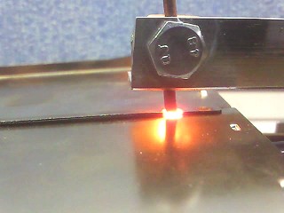
This spot welder using a limit switch, after lowering the upper electrode arm, it starts the welding process in a safe and proper manner. Firstly, timer waits for 1 second so that the user can tighten the electrodes and then it turns on the welding current for the time set by potentiometer in the range of 0-4 seconds. This allows both hands to be free and you do not have to use the foot switch.
Transformer:
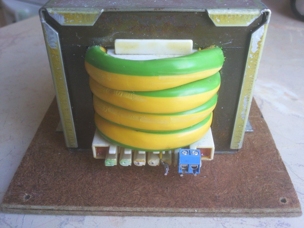
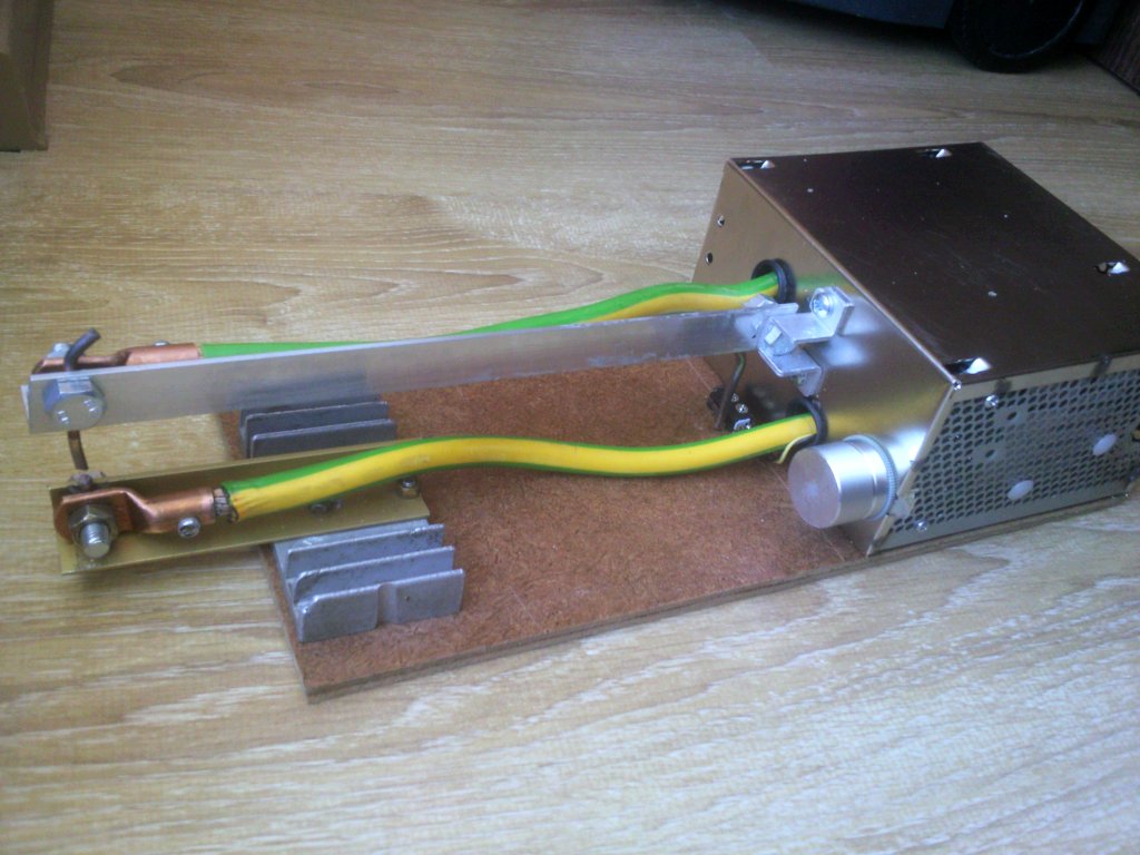
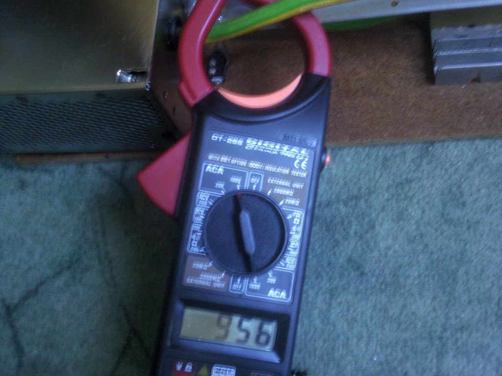
Transformer is a part of disassembled amplifier from Technics (SU-V670). Cross-section of the core is 23,5cm2. Although this dimension may seem to be rather small, the power of the transformer is significant enough. Secondary winding consists of almost 2 meters of line LGY 35mm2 (10mm of thickness plus isolation). Window with dimensions of 46,5mm x 9,5mm allows for placing 4 spools of the cable. At 660mV for a spool, 4 spools give 2,6V, at 950-1000A current with short-circuit. The transformer has one advantage in comparison with microwave transformers – it can be connected to the mains all the time and does not overheat. Due to that, there is no need to mount a fan to cool it. A number of holes in the housing provide passive cooling.
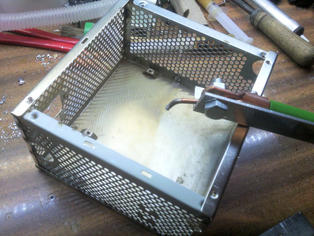
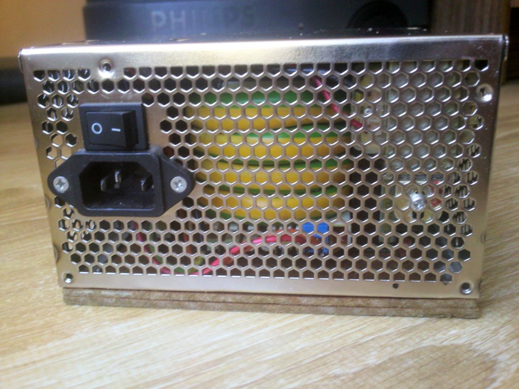
Construction:
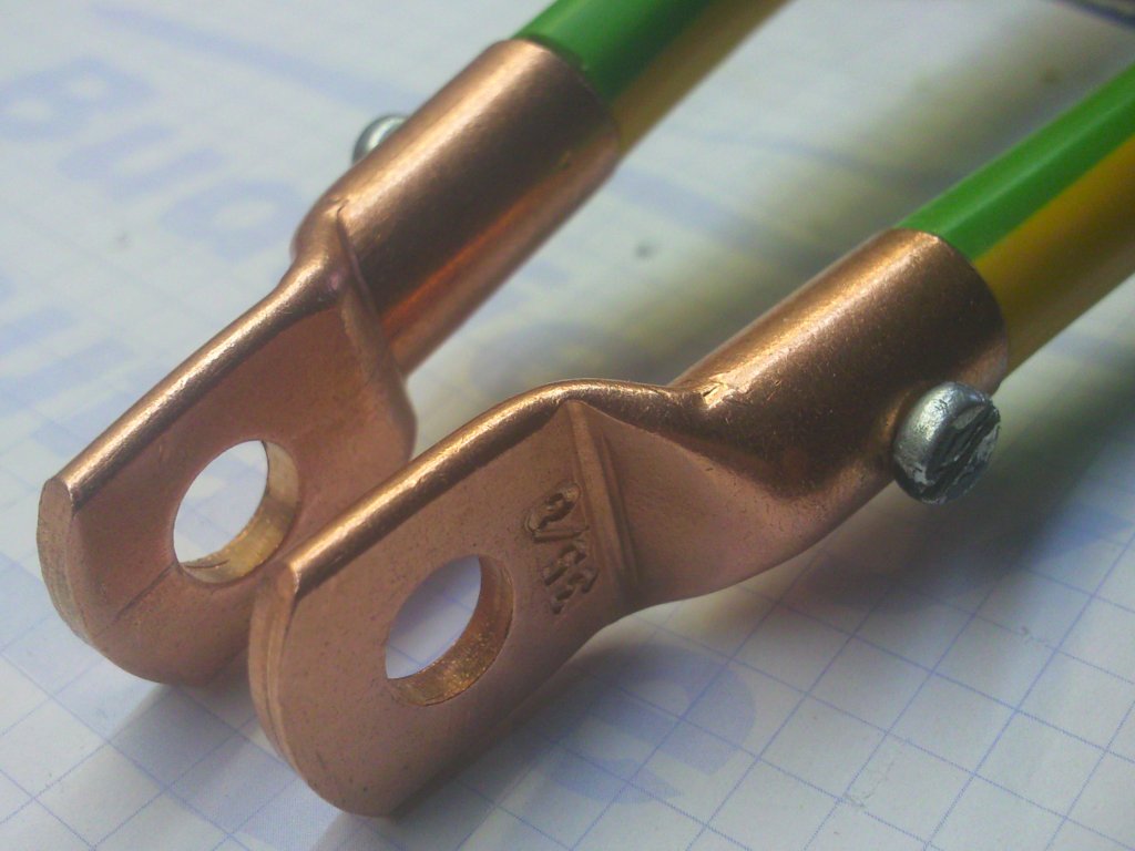
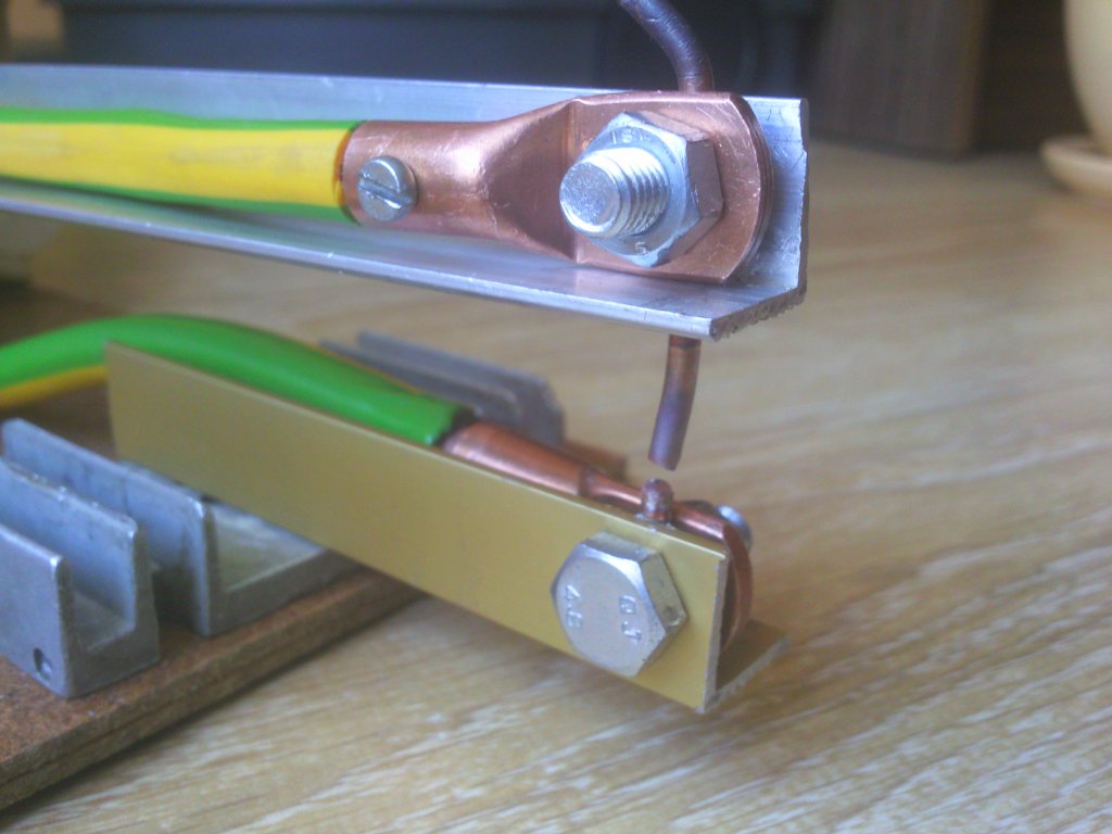
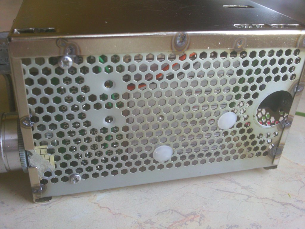
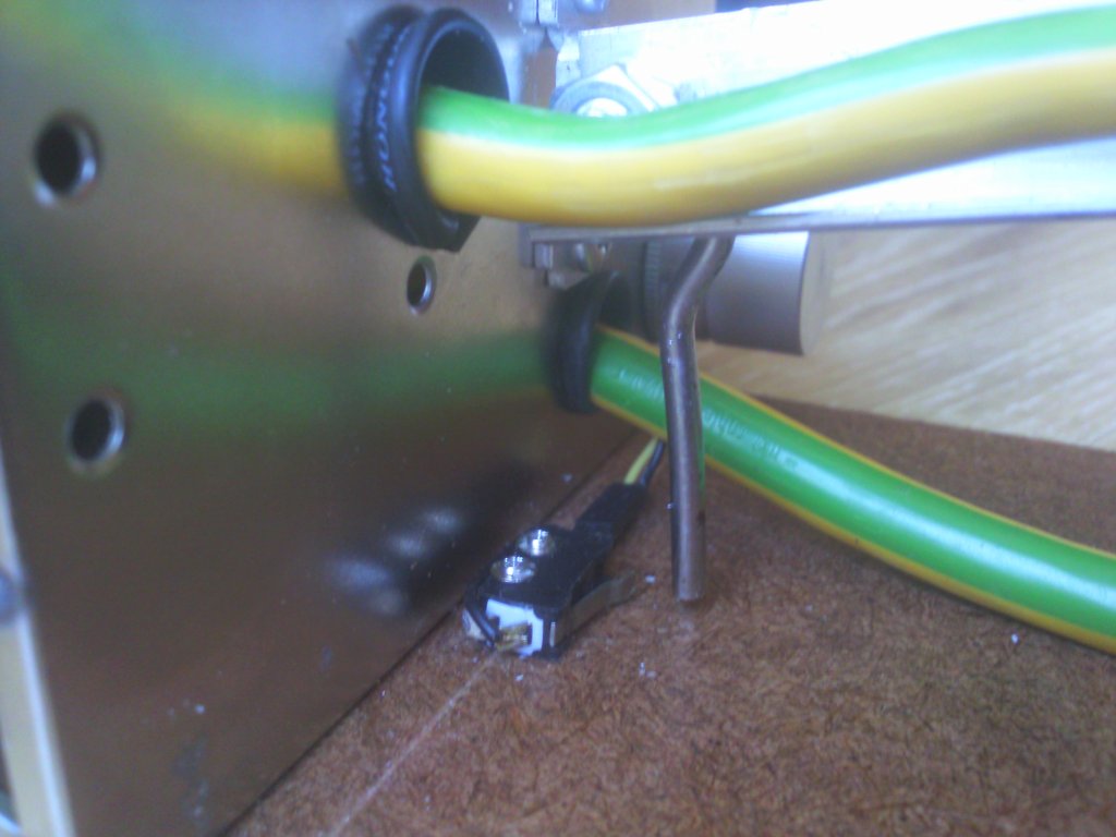
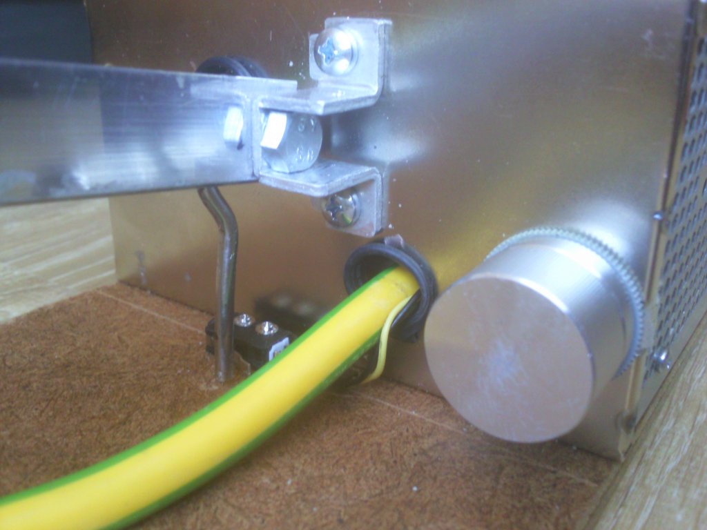
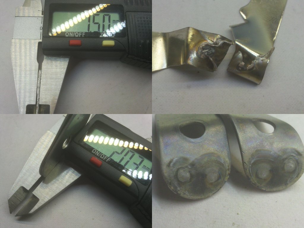
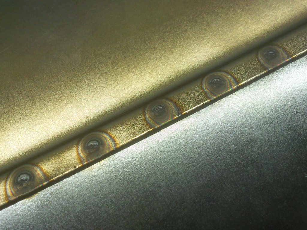
Housing of the transformer and electronics is made of elements of ATX power supply housings, combined together. Copper ring terminals 35mm2 were soldered at the ends of the secondary wire. Arms are the aluminum angles 2x2cm. They are also important since they dissipate heat from electrodes, what allows you to perform more weldings in a certain time. Electrodes are copper wires DY 10mm2 (approximately 3,5mm of diameter). They are tightened between the ring terminals and arms, 10mm screw, they pass through a 3,5mm hole in the screw. Such direct connection ensures very good electric contact and heat dissipation. Electrodes can be mounted at any angle of any length, so that you can reach different areas of the welded elements. Method of mounting prevents the electrodes shift even under strong pressure. Working length of arms is 24cm.
Timer:
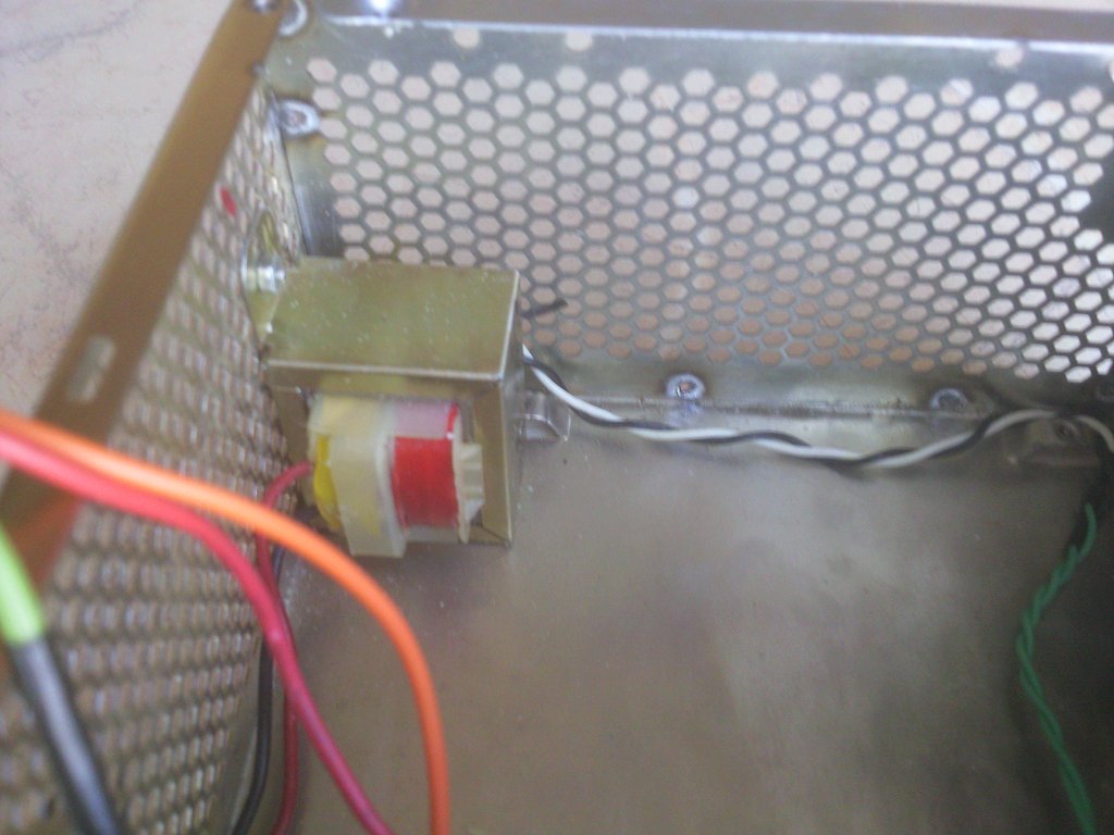
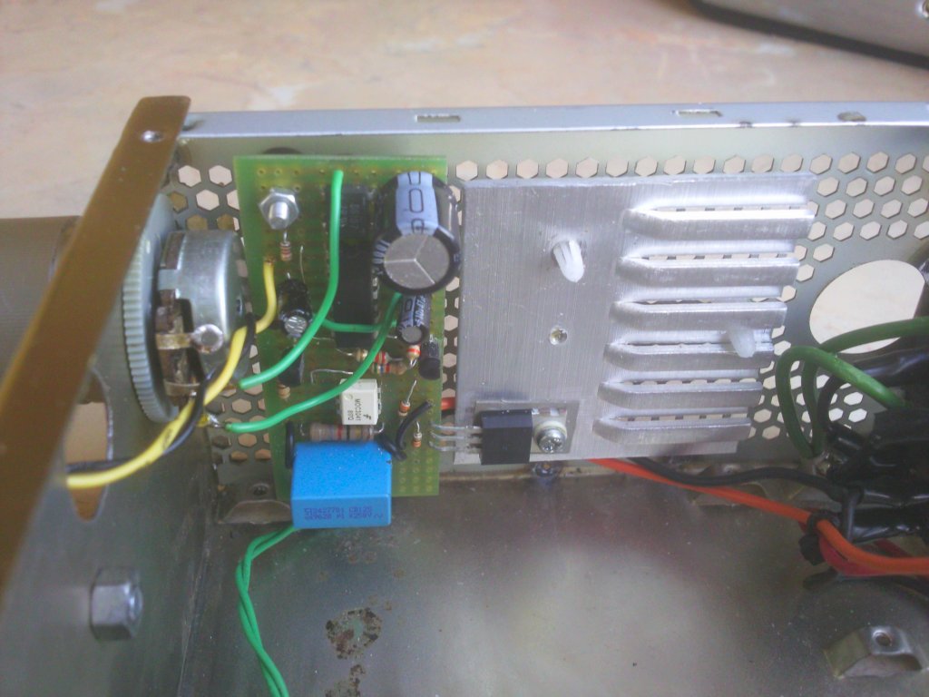
Limit switch is started by a “finger” mounted on the upper arm of electrode, which starts the timer. Timer is a simple circuit on 4 NAND gates included in the structure of logic system 4093. The first timer is set permanently and its time is 1 second. After this time, the second timer is unlocked. The second timer has a potentiometer for adjusting the time of welding in the RC circuit. Output of the last gate switches two NPN transistors (its capacity is only 0,5mA). The use of two NPN transistors is justified by the fact that if you used one PNP while pressing the button, there is a temporary loss of voltage to 8V at the output of the last gate. That loss is detected by the transistor and passed further. If you use NPN, this phenomenon does not occur, because it inverses the signal, so the second NPN is essential to inverse it back to the original state. The last NPN transistor switches optotriac MOC3041 with detection of mains zero, and the optotriac switches the triac BT138 which closes the circuit of the primary winding. The time circuit is powered from a small transformer 10V placed in the corner of housing. The rectified voltage is 14V.
User's safety:
While working with such a device, it is recommended to use at least an eyeshield. Even if the current is switched on and off at tightened electrodes, you can still be hit by a splinter. If you use a metal housing – it has to be grounded together with transformer and arms of electrodes. Triac does not require a big heat sink – small one should be enough. Double isolation means that the triac is isolated with silicone backing from the heat sink, then the heat sink is mounted to the housing by means of plastic spacers.
Pictures:

Video:
More details can be found HERE.
Link to original thread (useful attachment) - Półautomatyczna zgrzewarka punktowa 2,6V 1kA