Continue to Site

Welcome to EDAboard.com

Welcome to our site! EDAboard.com is an international Electronics Discussion Forum focused on EDA software, circuits, schematics, books, theory, papers, asic, pld, 8051, DSP, Network, RF, Analog Design, PCB, Service Manuals... and a whole lot more! To participate you need to register. Registration is free. Click here to register now.

ripple voltage blocker circuit for 24DCV 100A?

Status
Not open for further replies.

balagbc

Junior Member level 2
Joined
Sep 18, 2015
Messages
21
Helped
0
Reputation
0
Reaction score
0
Trophy points
1
Location
chennai
Activity points
175
hi folks,
my voltage(24v,100A) circuit producing 5v ripple i couldnt reduce the ripple voltage.if i use this voltage my equipment surely ll get damage . so wht i should do now ? how to reduce the ripple voltage ? capacitance in parallel not helping me ?pls suggest anyother method any other method?
 

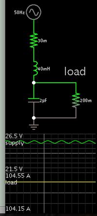
An inductor has the effect of reducing ripple. Then it is referred to as a 'choke'.

It is practical to do this because you have high current flow, therefore a small inductor is sufficient.


A miniscule capacitor value is used, to prove that the inductor can do a satisfactory job. Ripple is within 1 percent.
 
Its still a huge item, my 10 mH @12A DC weighs about 10 KG. If you are into winding items, then you could wind the choke on a much smaller iron core and use a second winding wired across the supply, the theory being that the DC in the second winding bucks the 100A, leaving the magnetic field to cope with the +-5A. Should reduce the weight of the iron by a factor of 20.
Frank
 
Its still a huge item, my 10 mH @12A DC weighs about 10 KG.

I believe you. Now that I think about it, the wire would need to be as substantial as automotive jumper cables. It would be wound around an iron core. Enough turns to reach 10 mH.
 
Looking back through some fairly ancient design notes I have kept, the figures I came up with for a 48v 100A single phase choke input filter design :

L1 = 1.3mH
C1= 55,000uF
That will produce a ripple voltage of roughly 2.5v rms at full load.

A second stage filter could be added to that to reduce the ripple further.
L2 = 1.3mH
C2 = 27,000uF

Suitable chokes might be a six inch stack of three inch laminations.
Eighteen turns of 50mm squared copper cable (8mm diameter round copper).
With about a 1.5mm air gap.
 
Last edited:
Is your ripple current 100/120Hz or are you using a switchmode to provide the current?
 

my voltage(24v,100A) circuit producing 5v ripple i couldnt reduce the ripple voltage.if i use this voltage my equipment surely ll get damage . so wht i should do now ? how to reduce the ripple voltage ? capacitance in parallel not helping me ?pls suggest anyother method any other method?

What is the source for your circuit? How you are deriving it? If possible post the circuit.
 

Hi,

I don't think you need the full 100A to power electronic circuit.
So you maybe need 100mA to supply your electronics.
Then create a branch with RC or LC rated for 100mA and filter your supply voltage, while the "power" branch still has the ripple...

Klaus
 

I assume from your location , and limited explanation, you mean 100Hz ripple on a 2.4kW linear power supply.

This is not a simple job.

1st you need to understand why it has ripple and what are the limitations of passive parts then specify a better design.
Before that, let me give you my definitions;

1. Ripple voltage = Vpp swing on the storage cap of a line frequency powered transformer diode bridge, where the charge currents begin at the sag voltage and charge up to the peak ( minus diode drops)
2. Tp = RpC or Parallel RC time constant= Storage caps * Load Resistance [ Rp//C ]
3. Ts = Rs *C or Series Time Constant of the Capacitors * the sum of series resistances from XFMR secondary to DIODEs in bridge to Storage Cap ESR
4. Load Regulation L.R error = drop in DC voltage due to load / no load voltage
5. Average/Peak Ratio = a conversion factor that affects no load voltage (peak) and Average Voltage with full load and also drops with Load Regulation error.
6. Power Loss in ripple voltage. Whereever the series resistance causes Vpp, at 100A there is significant power loss from Pd=Rs*I²

Now your problem is only excessive Vpp.

Now let me do some calculations

What is Rs? 50 mΩ
Given 100A with 5Vpp ripple then Rs= 5V/100= 50 mΩ where the average current 100A occurs between the +/- peaks of ripple.
This ripple in % is 5V/24= 20.8%

What is your load Res? 24V/100A= 240mΩ.


If you apply a rectified sine voltage to only 2 series resistors to ground, the load would see 50/(50+240)*100%=17%, which is pretty close to your % Ripple.

There is a relationship between the exponential decay or Tp=RpC time constant expressed as a multiplier of your charge interval , in this case 10ms.
Without looking it up I know 2% ripple is 5T and 27% ripple (1-1/e) is 1T.
So 20% ripple is around 1.8T= 18ms, where RL= 240mΩ so for Tp=RpC, C= 18ms/240mΩ = 75,000 uF is my guess.


Now the Ts=RsC = 50mΩ*75mF = 3750 microseconds [µs]

Now I happen to know that more expensive LOW ESR dielectric Caps in low voltage are around < 200us, There is a potential to replace all the caps with low ESR caps with a 100~150us series time constant and allow some Rs for the diodes and windings.

Which means you may have to double up on diode sizes to drop Rs or get better Caps or both.
My Rule of THumb is Rs in diodes = 1/Pd max power rating of diode. so for say 10% of total Rs = 50mΩ = 5mΩ, the power diodes must be rated for 1/0.005Ω = 200 Watts roughly of continuous heat-sinked power.


Since reducing Ripple Voltage %Vpp increases %Ipp ripple current by the inverse ratio.. i.e. 10% Vpp means Ipp= 1/10%=10x Imax dc
So your ripple current for 100A DC out with 20% ripple voltage is 500A peak-peak. roughly.


However this will increase the Peak current by reducing the ripple voltage as the duty cycle of charge pulses also is reduced by the same amount.

THis means we can apply an approximation of %Vpp= % duty Cycle of current = % (I avg/ I pk)

You will need to spread the ripple current over many Caps or find one huge 100mF Mainframe Computer grade super low ESR cap.

See where I'm going yet? (SMPS or many low ESR Caps and bigger diodes)

I'll leave the conclusions for later.
 
The traditional way to obtain very low ripple rectification (without an active regulator) is by using three phase mains.

A Single phase fullwave rectifier, without any filtering has 47% ripple at twice the powerline frequency
A Three phase fullwave rectifier, without any filtering has a 4% ripple at 6 times the powerline frequency. (*)

The initial ripple is much lower, the frequency is higher; the result is greatly reduced size, cost and weight of the filter components.

(*) Fairchild Semiconductor Voltage Regulator Handbook
 

The traditional way to obtain very low ripple rectification (without an active regulator) is by using three phase mains.
Have to agree, and I am fortunate enough to be able to do that here.

The original poster is located in India, and may not have three phases available.
A rather large LC filter, probably with two stages is very likely to be the most appropriate solution.
 

thanks for reply folks . got some ideas from ur reply's
 

from 3ph supply --->>step down transformer----->>bridge rectifier---->>filter capacitor---->>> load
 

Without Cap , the 3phase rectified ac voltage = Vp(1.65-1.5)/Vp *100%= 15% of peak voltage vs 100% for single phase. ( neglecting diode drops)

Harmonics start at 6f rather than 2f.

Does that help?
 
Even for the 3 phase Tx it is usual to have thyristor control (3 min) to give no load and max load regulation...
 
Status
Not open for further replies.

Part and Inventory Search

Welcome to EDABoard.com

Sponsor

Back
Top