N
naeem.saleem.ns@gmail.com
Guest
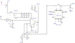
I am trying to implement a variable power supply in my circuitry built around OPAMP (LTC1637) negative feedback and NMOS (Farnell PartNo: 2114736) being a pass element. The idea is to supply the positive input (reference voltage) from a 12bit DAC and then vary the output voltage apprx 10mV steps from 2.8V to 18V DC.
When I started using this circuit, I faced few problems so I simplified the circuit top give a fixed reference voltage of apprx
3.3V (62K + 10K) (1/7.2 x 3.3 = 0.458),
Vout= 0.458 x (680+100)/100 = 3.5724V apprx
My input voltage for all the tests is 24V DC
I have connected a load that is variable resistor and it can take current from 16mA to 335mA approx. by rotating the POT
I am using R7 of 1R0 to sense the current. Circuit is designed so that current from 1mA to 350mA could be detected. This would be detected by using MAX9611 current sense IC that gives digital output (Max Full scale range of sense voltage as 440mV across 1R sense resistor is permissible as per datasheet)
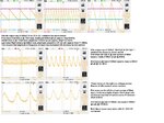
The problem I have is the ripple in output voltage
Initially I didn’t have any resistor at C1 (output capacitor)
I didn’t not have C8 across opamp o/p & negative i/p
My C9 initial value was 22nF
I started changing the circuitry and by trying different values of components, the best results I have so far is with 1000uF output cap @ C1. C9 as 47pF & C8 as 12pF. This has given me comparatively better results so far BUT they are still far away from being ideal as they are not acceptable for the type of voltage resolution and current measurement accuracy I am looking for.
The output ripple’s amplitude and frequency increases with increase in load current
Clearly this is not acceptable for the sort of accuracy am after. I was expecting this circuit to work like a normal voltage follower but for some reason it is showing nasty ripple at the output voltage. Please help
I have attached my schematic & oscilloscope traces with this post
When I started using this circuit, I faced few problems so I simplified the circuit top give a fixed reference voltage of apprx
3.3V (62K + 10K) (1/7.2 x 3.3 = 0.458),
Vout= 0.458 x (680+100)/100 = 3.5724V apprx
My input voltage for all the tests is 24V DC
I have connected a load that is variable resistor and it can take current from 16mA to 335mA approx. by rotating the POT
I am using R7 of 1R0 to sense the current. Circuit is designed so that current from 1mA to 350mA could be detected. This would be detected by using MAX9611 current sense IC that gives digital output (Max Full scale range of sense voltage as 440mV across 1R sense resistor is permissible as per datasheet)
The problem I have is the ripple in output voltage
Initially I didn’t have any resistor at C1 (output capacitor)
I didn’t not have C8 across opamp o/p & negative i/p
My C9 initial value was 22nF
I started changing the circuitry and by trying different values of components, the best results I have so far is with 1000uF output cap @ C1. C9 as 47pF & C8 as 12pF. This has given me comparatively better results so far BUT they are still far away from being ideal as they are not acceptable for the type of voltage resolution and current measurement accuracy I am looking for.
The output ripple’s amplitude and frequency increases with increase in load current
Clearly this is not acceptable for the sort of accuracy am after. I was expecting this circuit to work like a normal voltage follower but for some reason it is showing nasty ripple at the output voltage. Please help
I have attached my schematic & oscilloscope traces with this post