Vermes
Advanced Member level 4
Main assumptions:
- building a “bulb” with RGB and white colors
- the “bulb” must be powered by 230V and have a possibility to be mounted in E27 socket
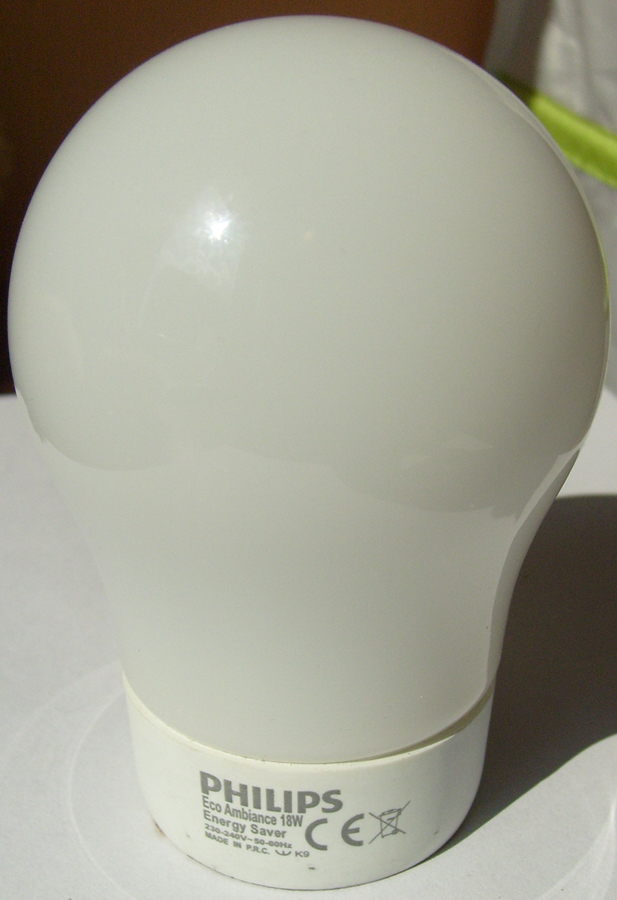
- the housing must be like a standard “bulb” - a standard ball
- a smooth light adjustment incorporating nonlinearity of human eye
- steering from an IR remote control
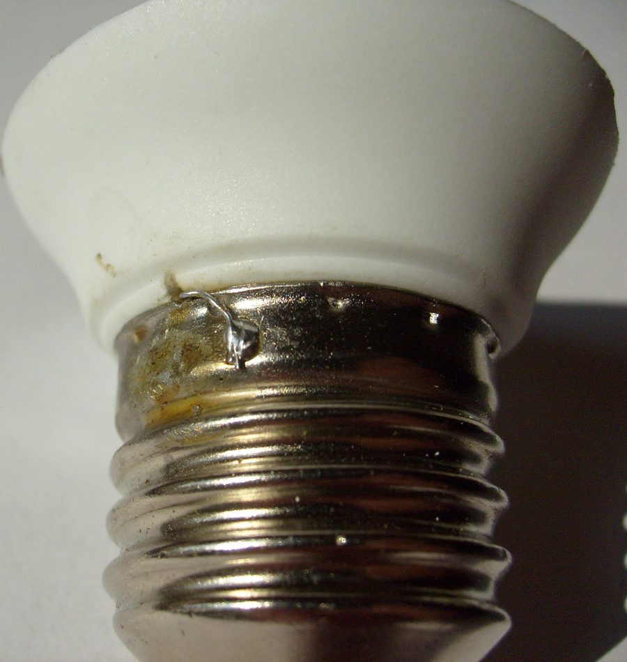
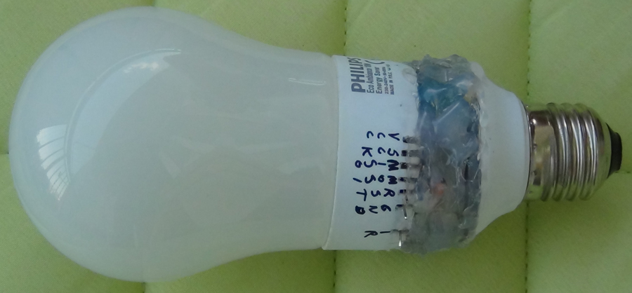
Problem 1 part 2: after cutting and opening the bulb it was found out that the lamp is spiral and it can be easily get out of the housing, therefore, it had to be crushed before it could be taken out. The bulb obtained some scratches inside during this operation. While that operations, one of the power wires broke off, soldering inside didn't succeed, therefore, the wire was soldered outside (fig.4)


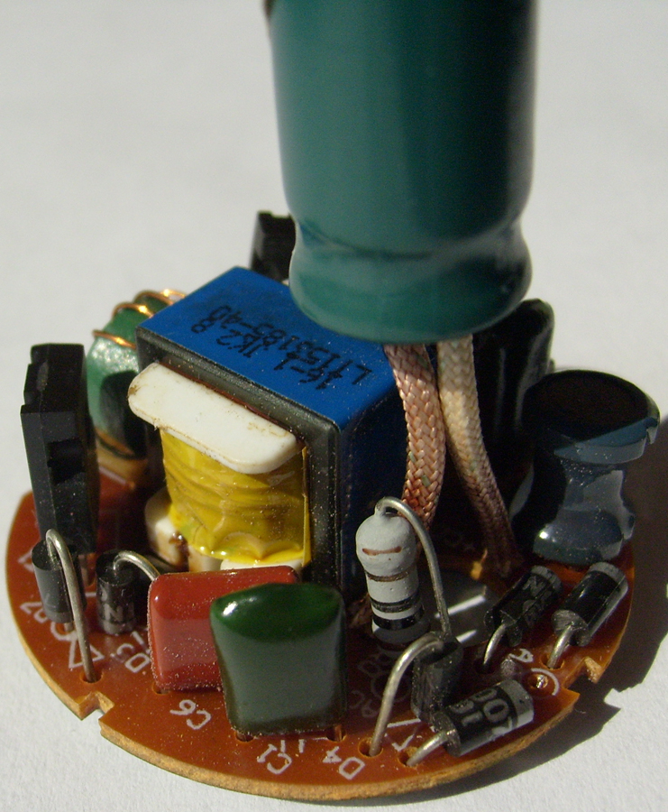
Problem 2: changing from 230AC to 5DC. Many possibilities were considered, starting from without a transformer, transistor interrupter reducing tension (buck converter / step down converter), ending on fly-back power supplies. Choice fell on fly-back.
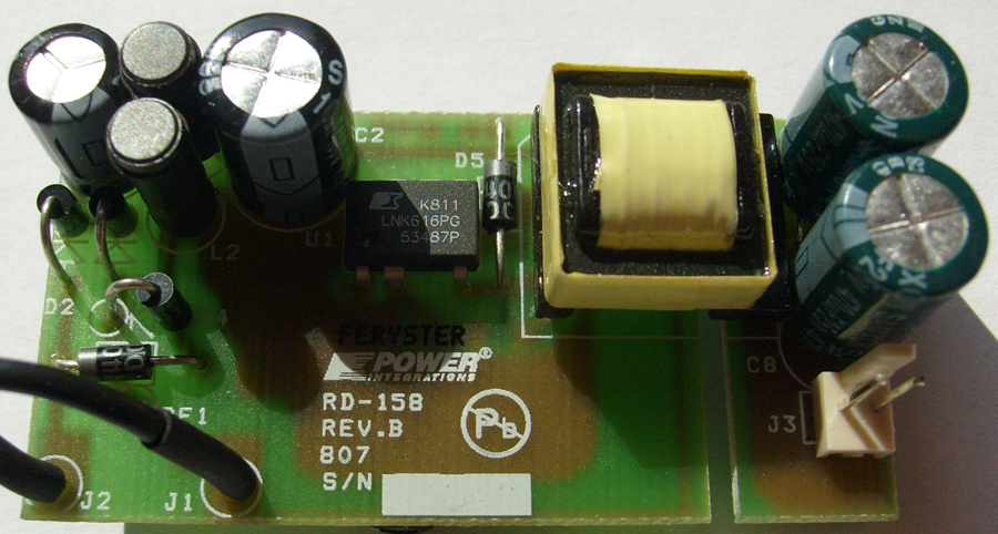
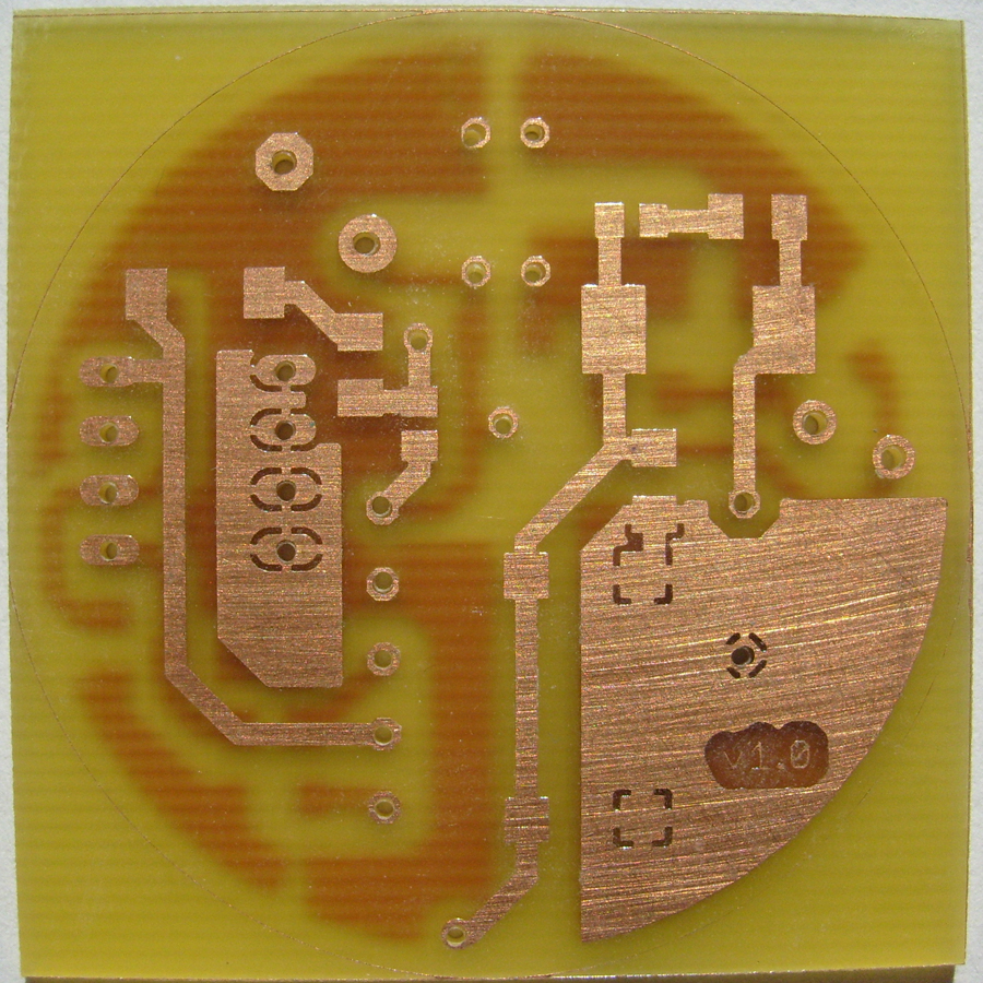
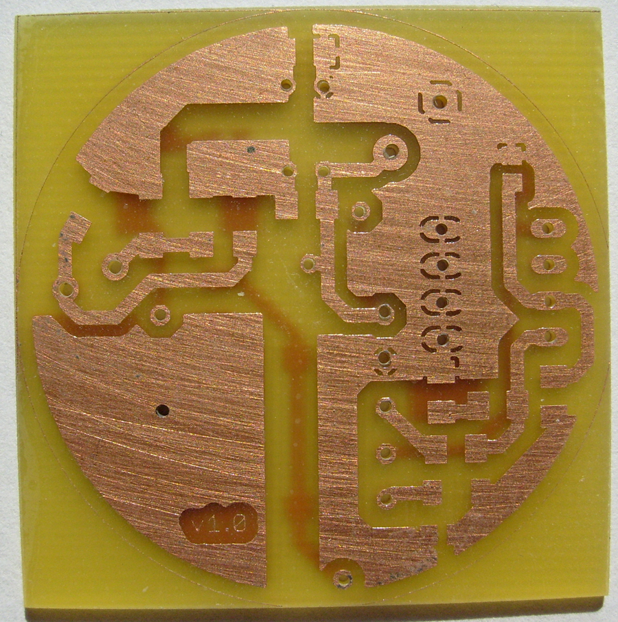
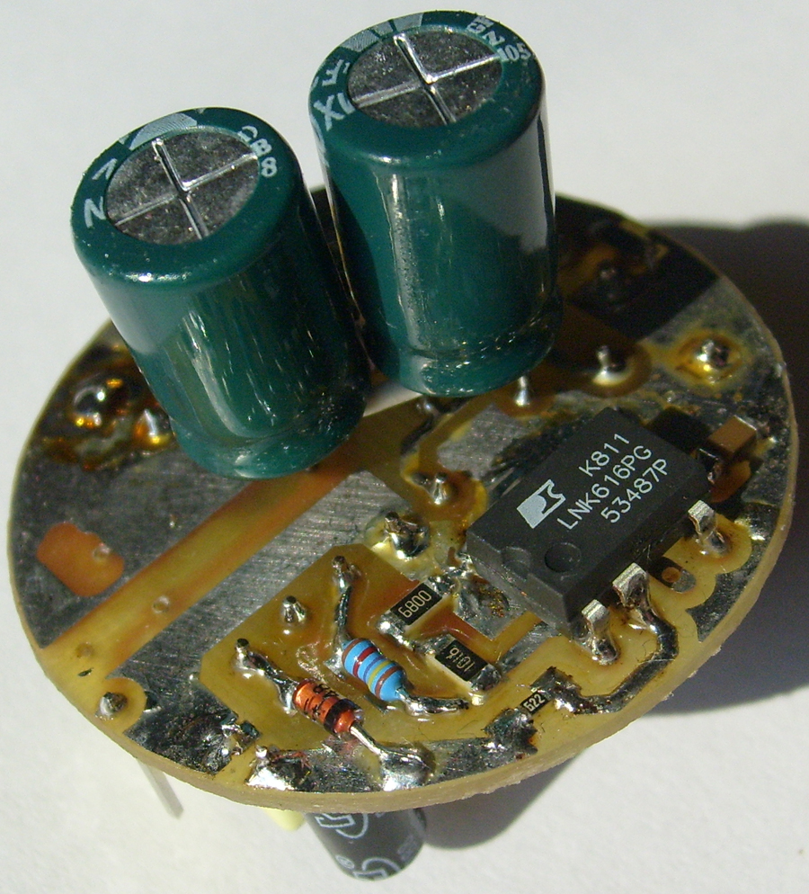
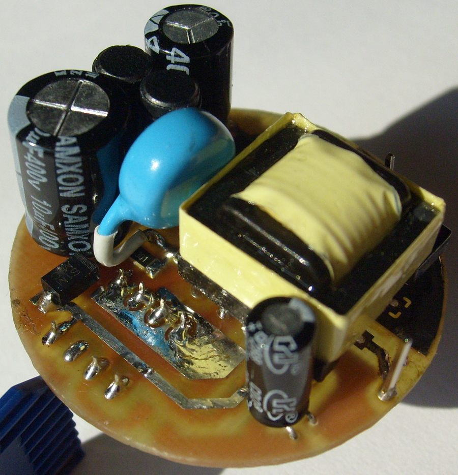
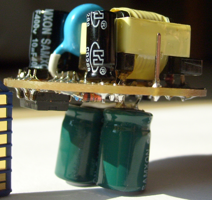
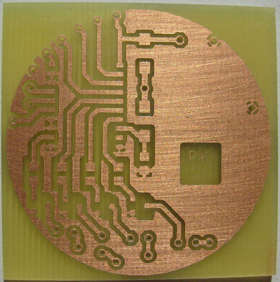
A RDR-158 (Reference Design Report) power supply was built – it can be easily found on google. The main elements of this circuit are: a transformer, coils and a LNK616 key (can be bought from Feryster). The designed PCB has a diameter of 4cm (the original is 64x33mm). Original on fig. 6,7 this one on the rest. The two capacitors seem ideally fit in an E27 screw,

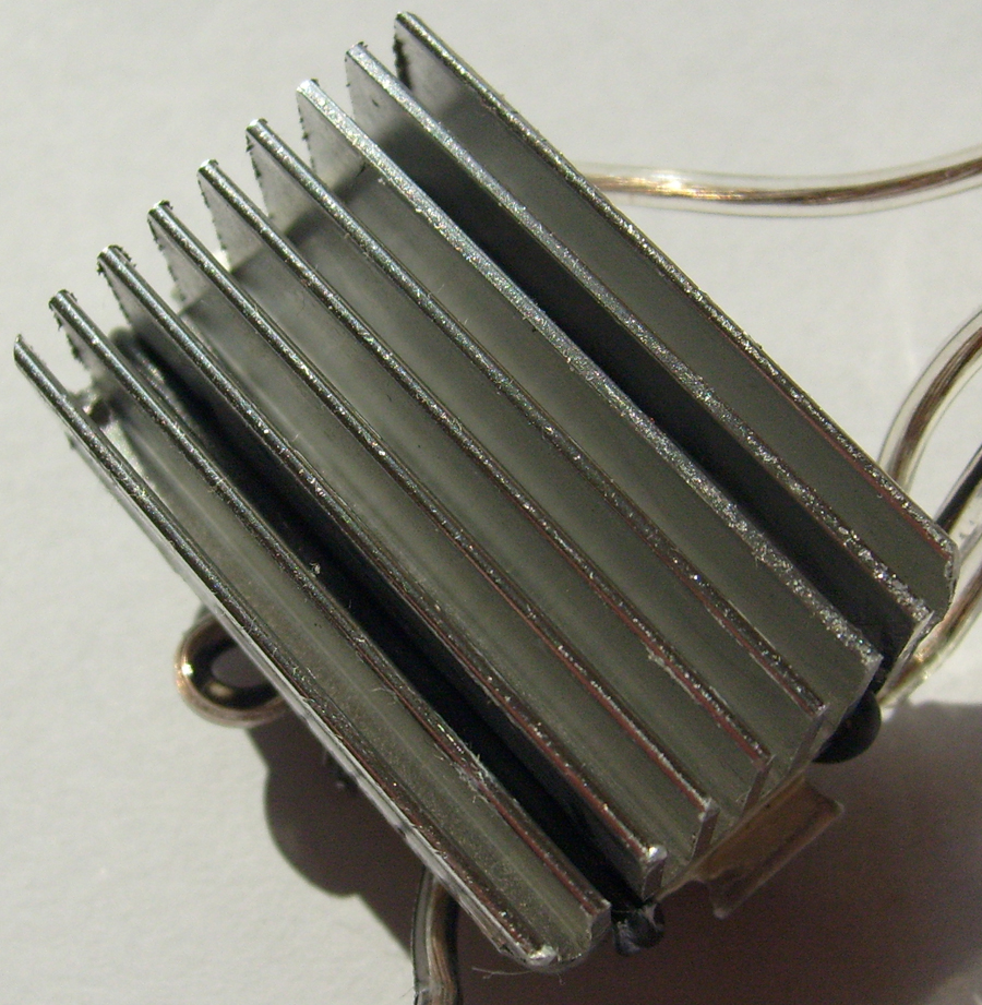
Problem 3: choosing the LEDs. This choice was quite quick, a RGB LED of 3x1W power was chosen and a white LED 5W. The diodes will heat, therefore, a heat sink was added (40x20x15mm), the diodes are attached to the heat sink by small isolated wires and between it and the heat sink, there is a thermal conductive silicon paste.

Problem 4: brain of construction and steering
The first choice fell on AtTiny2313 (2kB flash, 128B ram) it was too low, therefore, AtTiny4313 was used – flash is filled in 90% and ram in 60%.
All the diodes share the anode. N-Mosfet transistor used was IRLML2502, specification:
- voltage VGSTH=0.6-1.2V what is a very good choice, depending on that the steering is on uC 0-5V
- very low resistance on fully opened RDS=0.045Ohm got at 4A for VGS=2.4V
Adjusting the light is made by PWM, however, 4 8bit PWMs are used in this device. Each channel gives 2^b=256 levels of light, but to eliminate the nonlinearity of human eye, only 51 (50 levels + off state) levels were used. An algorithm was used, using float number, but it weighted too much and filled totally the flash, therefore, an arrayed values were counted and put in RAM.
The remote control is a Philips pilot from FWM-777 tower amplifier. It uses RC-5. The standard frequency receiver is used (36kHz), and the INT0 interruption is used.
Programs applied to uP:
- gradual brightening and dimming the LEDs – made by Volume+ and Volume-
- choosing defined colors: green, yellow, orange, red, pink, violet, blue, aqua – made again by Volume+ and Volume-
- smooth transitions between above colors (it goes around). Also made by Volume+ and Volume- (changing the speed of the transitions)
- in this program, every color lightness can be set manually. Volume+ and Volume- to change the lightness and Album+, Album- to change color
Additionally in 1-4 modes pressing and holding Play button sets the lightness to 100% and pressing and holding Stop sets lightness 0%. Pressing and holding Off button sets mode 1 and 0 filling.
After power outage, the bulb returns to the state in what it was earlier. How is it made:
From the fly-back power supply and trough the 1N4007 diode (in SMD), a 200uF capacitor is loaded (low ESR) and next to Vcc, however, to the analog comparator (in AtTiny4313) to AIN1 pin, trough 1N4007 diode (in SMD) power is set directly from the power supply, and finally, a resistor to GND 47kOhm. When a power outage is committed, the voltage rapidly goes to 0V, and the voltage on uC, thanks to the 200uF capacitor, lasts for a while. The fact of power outage is discovered by the comparator and it sets the right interruption. In this interruption, data is saved to EEPROM. The capacitor is so big that is lasts for saving 16B of data. When the power is back, the data is read from EEPROM.
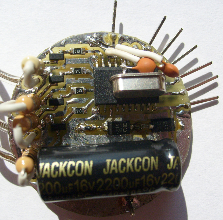
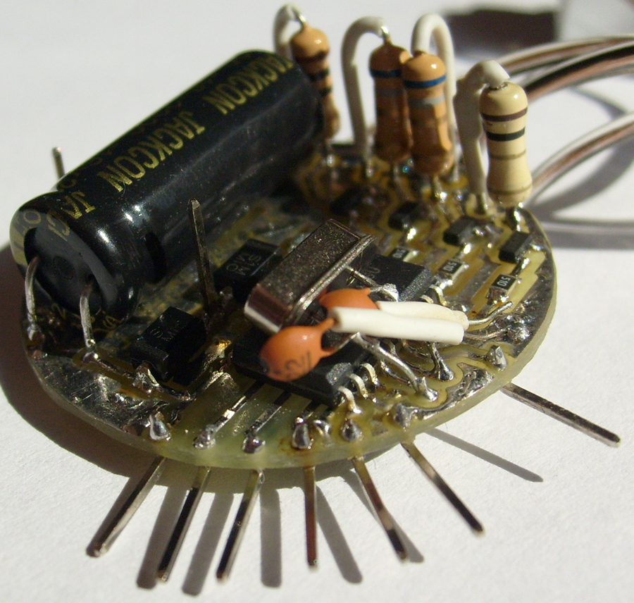
The above JACKSON capacitor (16V 2200uF) is too big for the housing, therefore, it was changed to a 6.3V 2000uF.
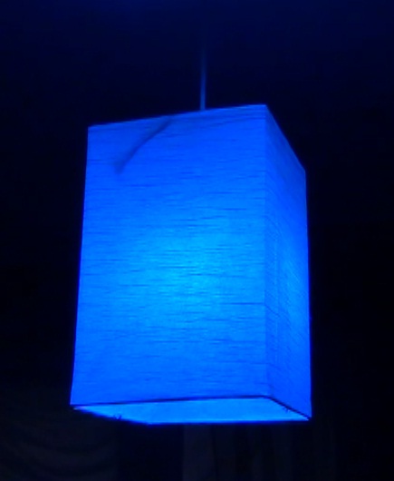
Final result:

Link to video:
Link to original thread – **broken link removed**