Welcome to our site! EDAboard.com is an international Electronics Discussion Forum focused on EDA software, circuits, schematics, books, theory, papers, asic, pld, 8051, DSP, Network, RF, Analog Design, PCB, Service Manuals... and a whole lot more! To participate you need to register. Registration is free. Click here to register now.
Hellow i want to make a circuit like a vu meter but with only 1 rgb led, when the frequentie is low, the red goes on, when middle, green en when high, bleu, can you help me find this circuit, thank you.
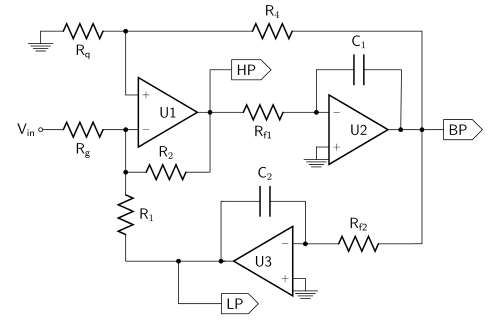
I'm sure others here will have a better way but you could use active (or passive if signal is strong enough) filters. LPF to FcLow which feeds into red led, HPF with FcHigh which feeds to blue and then a BPF which has cutoff of FcLow and FcHigh which feeds to green.
You would need a 2x resistor for each amp (6 total) 1 cap for each LPF and HPF (2 total) and then 2 caps for the BPF. 3 op-amps and then current limiting resistors at the output of each amplifier (3 total).
So 9 resistors, 4 caps and 3 op-amps. You may need another cap and resistor per amplifier if you don't have a dual supply so you can properly bias the AC audio signal for the op-amp.
You are confusing.
A VU meter shows levels, not frequencies. Do you want low levels, medium levels and high levels to show red, green and blue?
A spectrum analyser shows frequencies. Do you want red for low frequencies, green for medium frequencies and blue for high frequencies?
You would need a 2x resistor for each amp (6 total) 1 cap for each LPF and HPF (2 total) and then 2 caps for the BPF. 3 op-amps and then current limiting resistors at the output of each amplifier (3 total).
So 9 resistors, 4 caps and 3 op-amps. You may need another cap and resistor per amplifier if you don't have a dual supply so you can properly bias the AC audio signal for the op-amp.
The original idea, a simple light organ (see https://en.wikipedia.org/wiki/Light_organ) can be implemented as well. Similar to the suggestion in post #2, but preferably with an averaging rectifier after each filter. The visual effect is more impressive with separate LP, BP and HP frequencies instead of a single filter.
This site uses cookies to help personalise content, tailor your experience and to keep you logged in if you register.
By continuing to use this site, you are consenting to our use of cookies.