Continue to Site

Welcome to EDAboard.com

Welcome to our site! EDAboard.com is an international Electronics Discussion Forum focused on EDA software, circuits, schematics, books, theory, papers, asic, pld, 8051, DSP, Network, RF, Analog Design, PCB, Service Manuals... and a whole lot more! To participate you need to register. Registration is free. Click here to register now.

Review on zero cross detection circuit

Status
Not open for further replies.

pk_rulz

Newbie level 5
Joined
Nov 12, 2010
Messages
8
Helped
0
Reputation
0
Reaction score
0
Trophy points
1,281
Activity points
1,335
I have found a zero cross detection circuit at

I want to control a fan speed. So the zero cross detection is not very critical.
However I would like the power loss to be minimum. Also have been looking for low cost components.

Just wanted a review on this circuit. Does it seem rugged for commercial use.

Besides this since I also have a SMPS based 230V ac to 12V dc in my PCB. I was curious if I can use the same diode bridge of the SMPS instead of another one for this circuit. The issue seems to be the 22k resistor in the bridge which probably stops the capacitor from discharging through D3 and D4. A variant like https://obrazki.elektroda.pl/33_1305826805.png might be helpful with an intact diode bridge but I believe it greatly increases the power consumption.
 

Hi,

Don't use the same rectifier bridge, use independent.

Use 220k resistors with enough voltage rating.
Take care of safety regulations on pcb design regarding isolation between mains voltage circuit and low voltage circuit.

Klaus
 

Thanks KlausST. Any specific guideline on the safety regulation about pcb design that you are aware of.
 

You can use opto with bidirectional diode, so you don't need the rectifier
 

Hi,
Any specific guideline on the safety regulation about pcb design that you are aware of.
It depends on the country you live.

Klaus
 

You can use opto with bidirectional diode, so you don't need the rectifier

The problem is the cost increases much more than the price of 4 diodes when you go to a bidirectional one
 

The design worked flawlessly on breadboard.
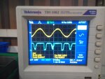
However when implemented on a PCB it shows noise in detection of one half cycle.
unspecified.jpg

The original circuit again


Any inputs why that would occur. One limitation is on my PCB is that the input to the optocoupler is longer parallel lines on the PCB around 6 cm long.

The input to the optocoupler also seems to be noise less. One possibility could be parasitic capacitance between input and output of the coupling. Any ideas ...
 
Last edited by a moderator:

Hi,

Try to connect a 10k in parallel to your optocoupler LED.

Klaus
 

Do u mean input to thee optocoupler ?
 

Hi,

LED, cathode & anode, input of optocoupler.

*****

this maybe improves the edges.

****
But I assume there is a problem with your PCB layout. Could you please show your PCB?

Klaus
 

Could not get into my lab today. Will check with the resistor first and update. The noise patterns are also a bit varying. Will send those pics as well.
 

Was able to access lab again today. You were right Klauss. The PCB layout was indeed faulty. The line connecting D1 and D2 was open circuit. Added a short across it and the circuit is working smoothly.

Thanks everyone for the help
 

Status
Not open for further replies.

Similar threads

Part and Inventory Search

Welcome to EDABoard.com

Sponsor

Back
Top