eepty
Full Member level 2

I am designing a MCU controlled open-collector digital output (MCU control the base of transistor as a switch, output low). The output is assumed max. 26Vdc, 85mA.
As transistor has max. reverse Vce of about 5V, I would like to add a reverse polarity protection for the output. In the other words, my device has no problem even the user collected the plus and negative wire wrongly.
I have considered some solutions:
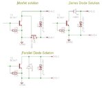
1. Simply add a forward bias diode in series with the output. The problem is that it will drop ~0.7V at the output.
2. Add N-channel mosfet at the low side of the output so that the mosfet will switch off when the polarity is reversed. The problem is the Vgs is not large enough to switch the mosfet fully on (When the transistor switch on, the collector will pull to ~0.1V)
3. Add a reverse bias diode parallel to the output. The problem is it will short circuit when the output polarity reversed. The diode will burn eventually.

Could you suggest other solution?
Thank you.
As transistor has max. reverse Vce of about 5V, I would like to add a reverse polarity protection for the output. In the other words, my device has no problem even the user collected the plus and negative wire wrongly.
I have considered some solutions:
1. Simply add a forward bias diode in series with the output. The problem is that it will drop ~0.7V at the output.
2. Add N-channel mosfet at the low side of the output so that the mosfet will switch off when the polarity is reversed. The problem is the Vgs is not large enough to switch the mosfet fully on (When the transistor switch on, the collector will pull to ~0.1V)
3. Add a reverse bias diode parallel to the output. The problem is it will short circuit when the output polarity reversed. The diode will burn eventually.

Could you suggest other solution?
Thank you.

