Continue to Site

Welcome to EDAboard.com

Welcome to our site! EDAboard.com is an international Electronics Discussion Forum focused on EDA software, circuits, schematics, books, theory, papers, asic, pld, 8051, DSP, Network, RF, Analog Design, PCB, Service Manuals... and a whole lot more! To participate you need to register. Registration is free. Click here to register now.

Replacing saw filter with LC band pass filter

Status
Not open for further replies.

ultrasonic.1991

Member level 3
Joined
Nov 6, 2015
Messages
60
Helped
0
Reputation
0
Reaction score
0
Trophy points
6
Activity points
554
hi i'm desiging a car remote transmitter for a car company by reverse enginnering and I can buy every component of the circuit in my country except one component which is a 433.92 MHz saw filter. i want to replace it with a LC bandpass filter that i attached. As far as i know the quality factor of saw filter is about 7500 which is at least a thousand times more than what we can achieve with LC filters. Can i use LC filter for this purpose? will there be interference with other RF devices if i use this filter?
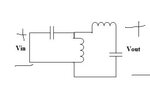
Drawing1.jpg
 

The question can't be answered without referring to the transmitter circuit. Does the transmitter have a crystal oscillator? In this case you don't necessarily need a SAW filter. A low pass is usually necessary to limit harmonics. If the SAW filter is however used to set the transmitter frequency, you'll need a crystal instead to achieve a stable oscillator frequency.
 
I think the confusion might come from the shape of the component. The flat 8-10mm round cans that look like SAW filters are actually just resonators. As FvM points out, all you need to do is make sure it transmits on the correct frequency, no filter, SAW or other, is needed.

Try using "433.92 resonator" as a search term, even Ebay returned 21 suppliers.

Brian.
 
thanks for your quick answers I attached the schematic of the circuit and a picture of the saw filter in the remote for clarification. This transmitter doesn't have a crystal oscillator.

New Bitmap Image.jpg

IMG-20200203-WA0009.jpg
 

I think that IS a crystal oscillator, or at least a SAW resonator oscillator.
Don't confuse the clock oscillator in the PIC for the one setting the transmission frequency.
I'm pretty sure you have some errors in that schematic too. It doesn't make sense to wire C1/C7 and C2/C8 like that.

Brian.
 

but based on the datasheet of PIC12f629 the external clock oscillator should be connected to pin 2 and 3 while it is connected to pin 6 as you can see. the PIC uses a 4 MHz internal oscillator.
 

The schematic has errors and isn't clearly labelled.

Pin 6 is the ICSP clock input, it is only used for that purpose when the IC is being programmed. At other times, it can be used as 'GP1' and in that circuit it is configured as an output. The PIC uses its internal clock generator in that design so it runs at 4MHz without any external frequency setting components.

The 433.92MHz oscillator is Q1 and the components around it, including SAW1. Pin 6 of the PIC produces a signal of highs and lows that make up the remote control data, the voltage is used to bias the oscillator on or off through R5. When pin 6 is high, the oscillator runs and it transmits 433.92MHz, when pin 6 is low, there is no bias to Q1 so the oscillator and transmitted signal stops.

Brian.
 
Status
Not open for further replies.

Similar threads

Part and Inventory Search

Welcome to EDABoard.com

Sponsor

Back
Top