me987
Newbie level 4
firstly I'm new to electronics project with some basic knowledge.
My project is "DAC controller"
The device is used to adjust the output voltage or current ( in that respective mode,the device works for both modes) based on the input vltg or current . ie as input raises the output should drop based on the scaled value from the microcontroller and vice versa as input drops output raises (can be considered as a comparator also).
Basically to understand in common words we are doing the job of a potentiometer(logic) in a digital meter,
i already have a demo model which is working fine but done by an another person.
I have got some knowledge on this spending these days but now im struck and i hope u guys can help me, thanks in advance.
microcontroller : msp430afe253
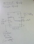
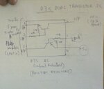
and from microcontroller 3 pwm output pins are considered . it is then connected to 3 different optocouplers(EL817,2nd pin input) and from optocoupler(4th pin output) it is connected to the "d3s" transistor mentioned above and the output is fed to View attachment emd3t2r-e rohm.pdf non inverting pin and output is fed back to inverting pin. This is the device output(opamp output pin)
i found out that any msp can generate a max of 3.5v (==msp ic vcc) but here in this device the output ranges from 0 to 5 v
from the above optocoupler connection i found out that the input voltage given to it is same as the output voltage(optocouler is mainly used here as a input output circuit isolater)
and opamp in that connection (maybe acts as a voltage follower, not sure)
so my doubt is from 3.5 to 5v how does it change, maybe only way is from the transistor ic i mentiond, but how?
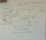
question: What does this d3s actually mean and what happens when connected this way(attached below)
My project is "DAC controller"
The device is used to adjust the output voltage or current ( in that respective mode,the device works for both modes) based on the input vltg or current . ie as input raises the output should drop based on the scaled value from the microcontroller and vice versa as input drops output raises (can be considered as a comparator also).
Basically to understand in common words we are doing the job of a potentiometer(logic) in a digital meter,
i already have a demo model which is working fine but done by an another person.
I have got some knowledge on this spending these days but now im struck and i hope u guys can help me, thanks in advance.
microcontroller : msp430afe253
and from microcontroller 3 pwm output pins are considered . it is then connected to 3 different optocouplers(EL817,2nd pin input) and from optocoupler(4th pin output) it is connected to the "d3s" transistor mentioned above and the output is fed to View attachment emd3t2r-e rohm.pdf
 non inverting pin and output is fed back to inverting pin. This is the device output(opamp output pin)
i found out that any msp can generate a max of 3.5v (==msp ic vcc) but here in this device the output ranges from 0 to 5 v
from the above optocoupler connection i found out that the input voltage given to it is same as the output voltage(optocouler is mainly used here as a input output circuit isolater)
and opamp in that connection (maybe acts as a voltage follower, not sure)
so my doubt is from 3.5 to 5v how does it change, maybe only way is from the transistor ic i mentiond, but how?
question: What does this d3s actually mean and what happens when connected this way(attached below)


