Continue to Site
Follow along with the video below to see how to install our site as a web app on your home screen.
Note: This feature may not be available in some browsers.
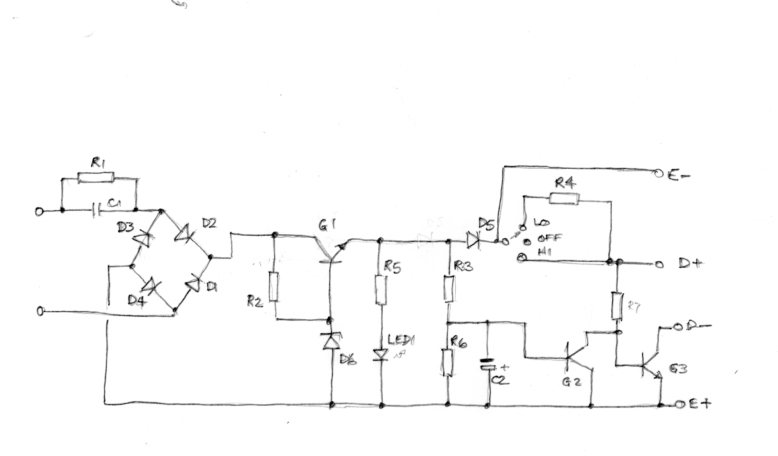
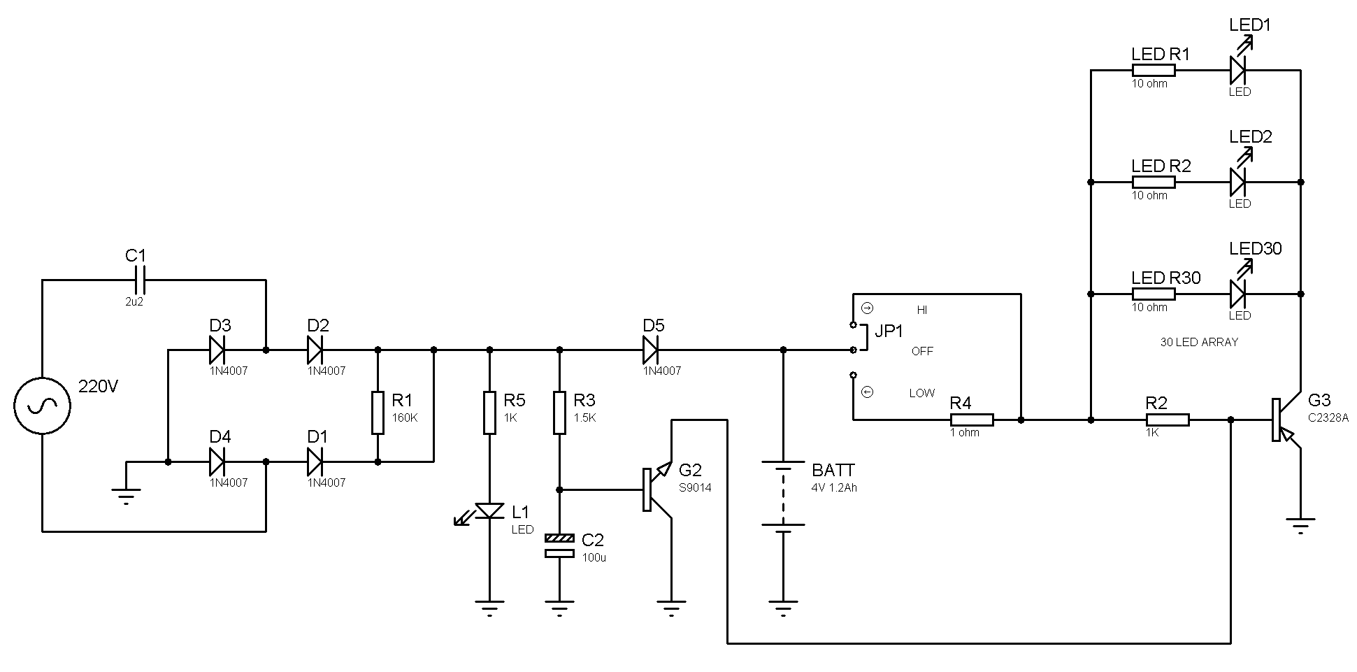
Can you please suggest the necessary corrections so that I can test it.
Also I can provide the Proteus ISIS or Multisim files.
The basic problem of missing charging control still needs to be fixed, e.g. by a 4.8 V shunt regulator in parallel to the battery.