Continue to Site

Welcome to EDAboard.com

Welcome to our site! EDAboard.com is an international Electronics Discussion Forum focused on EDA software, circuits, schematics, books, theory, papers, asic, pld, 8051, DSP, Network, RF, Analog Design, PCB, Service Manuals... and a whole lot more! To participate you need to register. Registration is free. Click here to register now.

R C Low pass filter not filtering at all

Status
Not open for further replies.

gonespa

Member level 1
Joined
Sep 10, 2012
Messages
32
Helped
2
Reputation
4
Reaction score
1
Trophy points
1,288
Activity points
1,654
Hi,

I am trying to measure (precission is not a concern) the current used by a RC brushed DC motor (the kind used on RC cars). The idea is to simply identify locked rotor conditions by measuring the current via ADC port of the PIC and comparing it continuously on software to a reference value. (I know this is not the best method, but I am trying just to experiment).

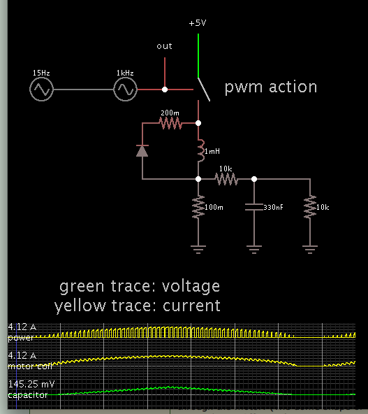
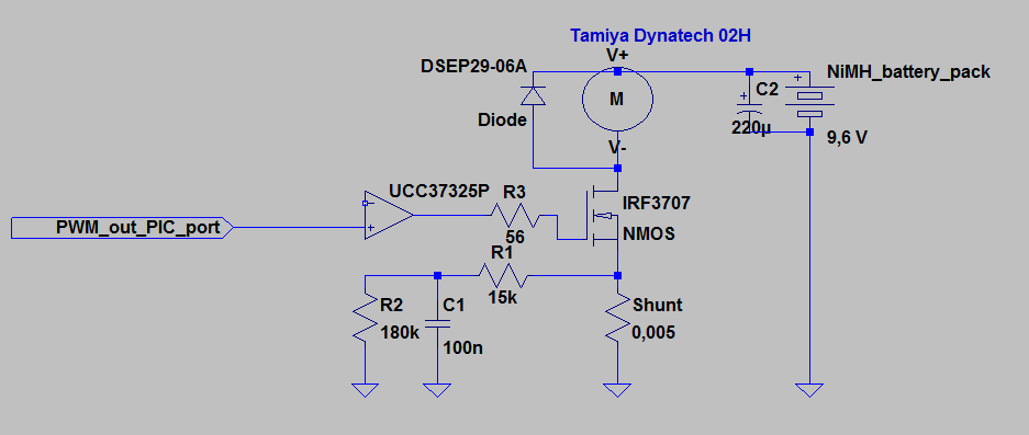
To control the speed I am using a PIC microcontroller, PWM at about 20 KHz, a mosfer controller UCC37325P and a MOSFET IRF3707 protected by a fast diode DSEP 29-06A. (in a low-side drive configuration).

To measure the current, a simple piece of wire in a breadboard of about 5cm is being used as a shunt (22 AWG, 5cm length , equals about 0,005 Ohm, in fact I made a small circuit in the breadboard to check this value, obtaining a resistance of 0,00538 Ohm).

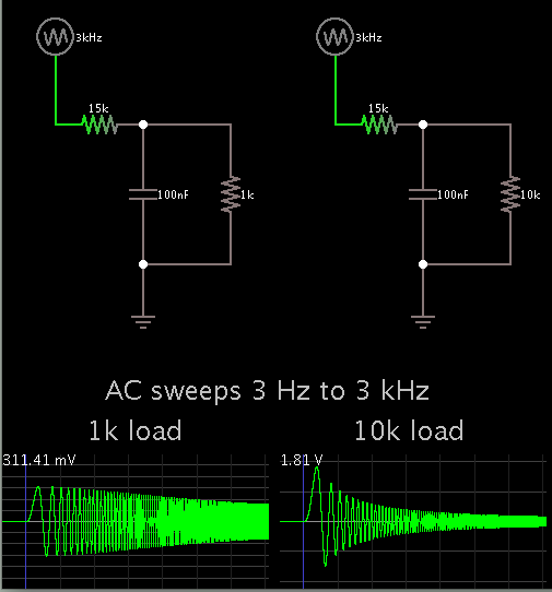
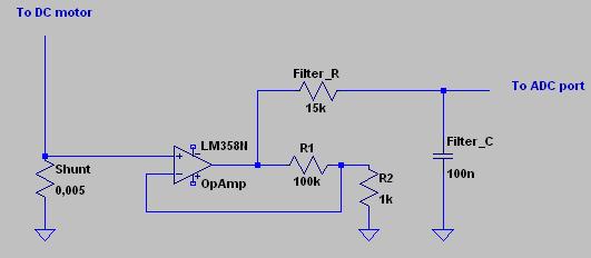
I measured the locked rotor condition current with a multimeter of about 7 Amps so, initially, I thought abaout programming to PIC to detect a condition where the motor used more than 3 Amps, just to check the concept. I decided to use low pass filter with a frequency cutt-off of about 100Hz (Resistance = 15K in series, Capacitor 100nF to ground) and feed that output to the non inverting input of an Opamp (LM358N series), obtaining a 101 Gain through a 100K resistor to the inverting input, 1K from there to ground. Opamp Output directly connects to ADC port.

With this values, at 7 amps, Voltage should be to 3.535 Volts (considering the OpAmps is not rail to rail and so will never output 5 volts, by the way the voltage fed to it). At 3 amps, 1,515 Volts.

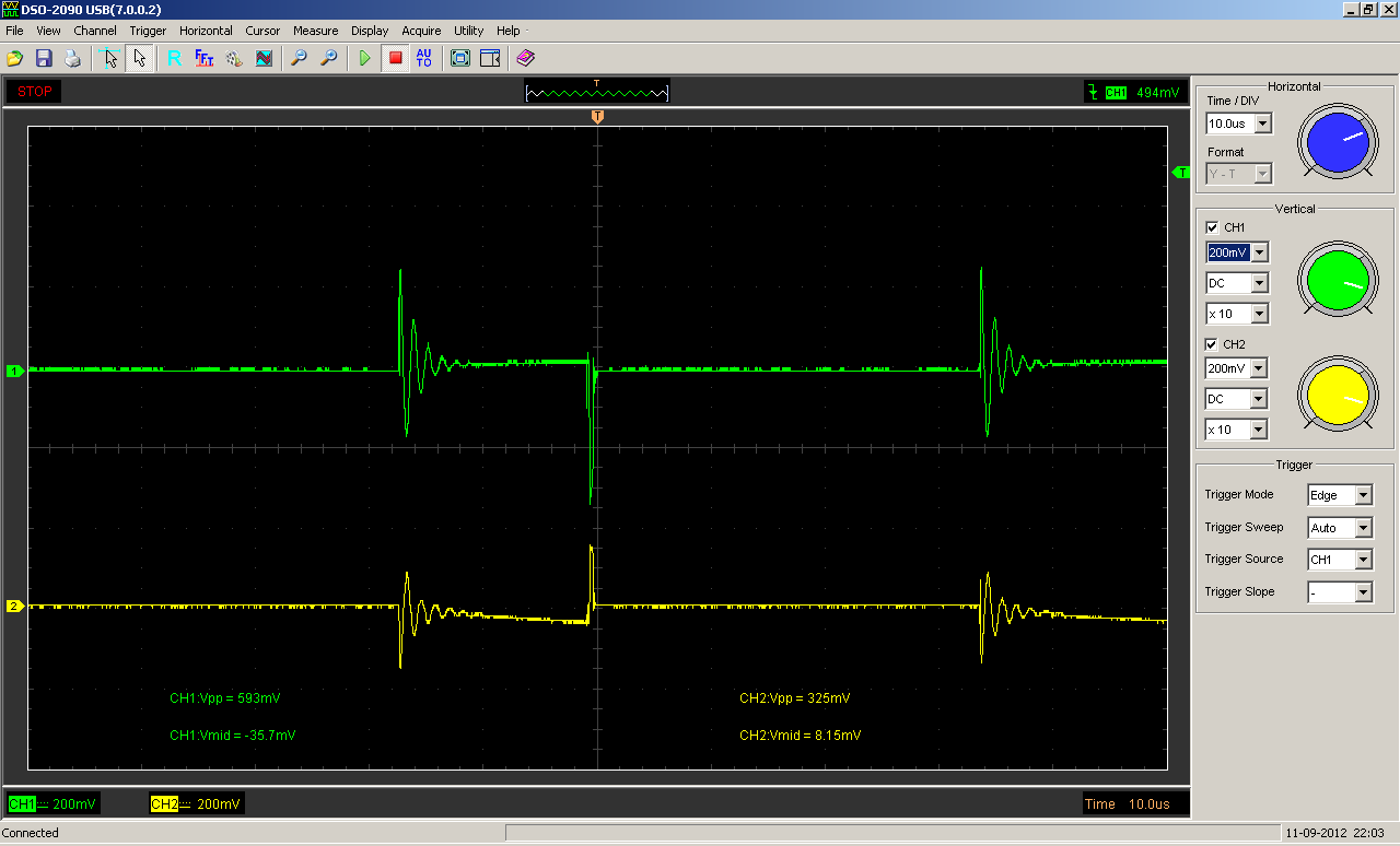
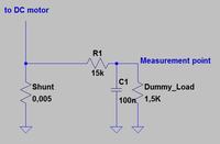
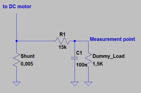
The thing is, measuring voltage in the output of the opamp shows the RC filtering is not doing it´s work. I order to simplify all this and to ensure the ADC port or the Opamp is not influencing in this, I just eliminated the opamp completelly and simply connected the RC filter to the Shunt, and a dummy Load (resistance of 1,5K), and obtained the attached oscilloscope measurement


This is basically a reduced version (in terms of voltage) of the MOSFET switching waveforms.

The simplified part of the circuit where voltage measurement is made


Does anybody know what can be happening here?
 
Last edited:

The filter in the diagram has a cutoff frequency of about 1kHz because the 1.5k resistor plays a dominant role; however could you post also the voltage measured at the input of the filter (i.e. directly on the shunt) in the same conditions you get the oscilloscope picture you posted ?
 
It may be a problem with grounding. The motor current flows somewhere through "ground" wires. Since those wires have some resistance, there is a voltage across them proportional to the motor current. You may be measuring the difference in voltage between two "ground" points (in addition to the wanted signal).
 
Looking at the 1k load... This is draining a lot of the signal.

Try a higher resistance load.

Here is my simulation with frequency sweeps:

 
How is that cutt-off frequency calculated? I assumed the 1,5k ohm simply added to the 15k ohm resistance resulting in a 16,5k ,100nf R C Filter (obviously i was wrong). By the way, I used this webpage to calculate cut-off frequency:

**broken link removed**

I will post the oscilloscope trace you request whenever i hit home, but if i recall correctly the waveform is approximately the same.

Before discarding the opamp amplificator, I tried filtering the signal by using active filtering (using the opamp and the divided feedback resistors to inverting input, plus paralleling the resistor which goes from opamp output to inverting input with the 100nF cap): Same problem, no filtering. However, when I moved the RC filter from the input of the opamp to the output (between opamp and ADC port) it worked (however the gain was not 101 but something higher, I did not calculated it).

- - - Updated - - -

Hi, I must tell (I ommited it but I am starting to think it is very important) that my circuit is on a breadboard, so you can imagine that circuit layout is far from perfect. However, for the oscilloscope trace i placed the ground clip of the probe directly across the "dummy_load" resistance. Where should I place it to minimize that effect? Close to the battery ground?.
 

The effective low-pass R is 1.5k || 15 k = 1.36k rather than 1.5k + 15k. But it still doesn't explain the observed waveform.

Although a first order filter won't remove all switching transient, the signal should look at least more smoothly. So bad measurement setup, as suggested by godfreyl is the only plausible explanation. For a comparison, you can tap the filter output signal with a coaxial cable soldered directly to the filter capacitor.
 
Looking at the 1k load... This is draining a lot of the signal.

Try a higher resistance load.

Here is my simulation with frequency sweeps:


I will try that too thanks, since now I see I was not calculating correctly the effective R for the filter
 

The filter in the diagram has a cutoff frequency of about 1kHz because the 1.5k resistor plays a dominant role; however could you post also the voltage measured at the input of the filter (i.e. directly on the shunt) in the same conditions you get the oscilloscope picture you posted ?

Here is the oscilloscope trace with both voltage across the shunt (CH1) and from the output of the filter ("dummy_load" resistor upper leg) to the same ground reference used in CH1 (CH2). I fixed both probes ground crocodile clips together and to the shunt leg connected to circuit ground. This is still with the 1,5k Ohm load. I have yet to test if with a much higher value as sugested by BradtheRad.


- - - Updated - - -

Looking at the 1k load... This is draining a lot of the signal.

Try a higher resistance load.

Here is my simulation with frequency sweeps:


Tried with 180K dummy load, the results are not much better...


- - - Updated - - -

The effective low-pass R is 1.5k || 15 k = 1.36k rather than 1.5k + 15k. But it still doesn't explain the observed waveform.

Although a first order filter won't remove all switching transient, the signal should look at least more smoothly. So bad measurement setup, as suggested by godfreyl is the only plausible explanation. For a comparison, you can tap the filter output signal with a coaxial cable soldered directly to the filter capacitor.

I tried making the same measurement I did from the filter output, but this time putting ground reference of the probe to a "different ground" this time much closer to the battery ground and to the motor, (at the other side of the breadboard), this time the result is MUCH worse.


So, the question is, how would I need to measure this with the oscilloscope?. I can imagine that if I want to use the ADC port of the PIC, the valid reference would be as close as possible to the ground pin of the Micro, is this correct?.

Anyways, as I stated somewhere before, I achived some level of success by putting the RC filter between the opamp and the ADC pin. This way I was able to see a satisfactory level of filtering. How is this possible?, since theorically that arrangement would amplify 101 times the unfiltered signal...
 

It seems you have a grounding problem. The signal you captured is not passing through the filter. You can try to:

1. Shorten the ground wire from circuit ground to probe as much as possible
2. Make a differential measurement: connect a probe to CH1, another to CH2. The ground wires of the two probes connected toghther a to any other point. Then connect the center tip of CH1 to Vout and tip of CH2 to ground of the circuit. Set the scope to visualize CH1-CH2. If the circuit ground is isolated from the main earth it should work.

Thanks, I will try that, but How can this other variant be filtering? It is the only way I managed to obtain decent results:


Looking closely at your scope traces...

It looks as though you are pulsing the motor at about 60 percent duty cycle. That appears to be the On time anyway.

The coil rings with greater amplitude after switch-off (as compared to switch-on). That is not unusual.

I believe your goal is to filter out the AC part of the ringing? That is the chief noise on your signal.

During 'Off' time, we do not necessarily expect the reading to fall to zero. Inductive action wants to continue pulling current around the power loop (or any available loop). This may be happening in your case.

So the question arises: Is current going through the shunt during Off time? Furthermore could the ringing be on a resonant frequency involving your filter capacitor?

Although you installed a 15k resistor, there may be another current/voltage path that the motor coil is acting through.

Just seeing what results from some brainstorming.

Coils have a way of making odd things happen when you switch current through them. Did you try using a resistive load instead of the motor? That will tell you a lot as to whether your filter arrangement is working.

I think I will post a complete diagram of the circuit, just in case. I will try to test the diferrential method sugested by albbg. If I understand correctly, choosing a common ground point for the two probes (The noisy ground will be shared by both probes), measuring with one one leg of the "load" resistor and with the other probe the other leg this noise should cancel out, right? or am I misunderstanding?.

I will post measurements of drain to source MOSFET voltage compared to the voltages droped by the shunt too. If I recall correctly, that weird ringing at the turn-off of the MOSFET is not present in the MOSFET itself.

I could use a resistive load but that would produce no ringing so, how would I know if I am filtering any AC component?.

I think I can see a subtle ramp down in the voltage when the MOSFET is off, possibly indicating current is still flowing and slowly decreasing?

The overall goal of all this is to obtain a rough estimation of the current flowing through the motor. In order to ease the work for the Micro, I was trying to reject as much noise from the switching as possible.
 

I made a simulation which ought to be close to your setup.

Screenshot:


It shows that your current monitor ought to work.

Notice the capacitor charge follows the triangle shape of current going from the power source through the motor. (The dome shape of current at the motor has current continuing due to diode action during Off-time.)

I adjusted values to suit the simulator. Nevertheless I believe the concept is very similar to yours.
 
Last edited:
I will post measurements of drain to source MOSFET voltage compared to the voltages droped by the shunt too. If I recall correctly, that weird ringing at the turn-off of the MOSFET is not present in the MOSFET itself.

I could use a resistive load but that would produce no ringing so, how would I know if I am filtering any AC component?.

I think I can see a subtle ramp down in the voltage when the MOSFET is off, possibly indicating current is still flowing and slowly decreasing?

Yes, this is why I asked if you had tried a resistive load.

While the mosfet is off, your scope trace would fall to zero. Or should fall to zero. A resistive load would let you test your setup without the somewhat unpredictable nature of a switched coil.

Because when looking back to your OP:

PWM at about 20 KHz, a mosfer controller UCC37325P and a MOSFET IRF3707 protected by a fast diode DSEP 29-06A. (in a low-side drive configuration).

I wasn't sure if this meant you installed a diode across the motor. (My simulation does.)

If no diode is across the motor, and you have a volt reading during Off-time...

Then it means current is going through your motor during Off-time...

And it suggests current is going through your mosfet when it should be off. Of course we can't be certain as to your motor's characteristics.

But suppose your low-pass filter is working? And suppose your motor is generating ringing with an amplitude of tens or hundreds of volts? That could still show up on your scope. (My simulation has it producing over 1000 volts, but I'm not claiming that your motor behaves exactly the same.)

Again I can't be sure that is really what's happening, but it is a way to explain the ringing waveform that was supposed to be gone.
 
  • Like
Reactions: gonespa

    V

    Points: 2
    Helpful Answer Positive Rating

    gonespa

    Points: 2
    Helpful Answer Positive Rating
hey FvM,
I am wondering why its in ll rather than series?
K

It seems, FvM is not available - thus, I will answer:

* Try to calculate the transfer function and you will be convinced
* The corner frequency (3db) is the inverse of the time constant tau. And tau is the product of C and the resistors which determine discharging of the C. Here, both R's act in parallel.
 
Basically, an electrical filter is a circuit that can be designed to modify, reshape or reject all unwanted frequencies of an electrical signal and accept or pass only those signals wanted by the circuits designer. In other words they "filter-out" unwanted signals and an ideal filter will separate and pass sinusoidal input signals based upon their frequency.
 

Yes, this is why I asked if you had tried a resistive load.

While the mosfet is off, your scope trace would fall to zero. Or should fall to zero. A resistive load would let you test your setup without the somewhat unpredictable nature of a switched coil.

Because when looking back to your OP:


I wasn't sure if this meant you installed a diode across the motor. (My simulation does.)

If no diode is across the motor, and you have a volt reading during Off-time...

Then it means current is going through your motor during Off-time...

And it suggests current is going through your mosfet when it should be off. Of course we can't be certain as to your motor's characteristics.

But suppose your low-pass filter is working? And suppose your motor is generating ringing with an amplitude of tens or hundreds of volts? That could still show up on your scope. (My simulation has it producing over 1000 volts, but I'm not claiming that your motor behaves exactly the same.)

Again I can't be sure that is really what's happening, but it is a way to explain the ringing waveform that was supposed to be gone.

This is the circuit. I ommited irrelevant components as the PIC itself, a linear potentiometer which is used as throttle input to the PIC, a linear voltage regulator to regulate voltage to 5v for the Micro as well as bypass capacitors to PIC and regulator (Oh, and a led connected to an output of the PIC to show it is up and running).


I will try a resistor as a load, but I am interested in rejecting or dealing with the kind of noise a DC motor introduces in a circuit since the final goal is to measure the load / current used by a motor.

By the way, I found motor specs on the Inet (I don´t know if they are accurate since I operate the motor a bit above recommended voltage, and, for example, at 9,2 volt I measured something between 7 and 8 Amps stalled...):

Dynatech 02H
Usable voltage: 7,2V - 8,4V

Torque at best efficiency: 413g-cm (7,2V)

R.P.M. at best efficiency: 25.000rpm (7,2V)

Current drain at best efficiency: 19,3A (7,2V)

Best efficiency: 74% (7,2V)


Regards.
 

It seems, FvM is not available - thus, I will answer:

* Try to calculate the transfer function and you will be convinced
* The corner frequency (3db) is the inverse of the time constant tau. And tau is the product of C and the resistors which determine discharging of the C. Here, both R's act in parallel.

You are right there LvW, I worked it out but found the gain to be Load_R/(Load_R+R1)! So for Big loads the filter isnt very effective? Is that a correct observation?

- - - Updated - - -

It seems, FvM is not available - thus, I will answer:

* Try to calculate the transfer function and you will be convinced
* The corner frequency (3db) is the inverse of the time constant tau. And tau is the product of C and the resistors which determine discharging of the C. Here, both R's act in parallel.

You are right there LvW, I worked it out but found the gain to be Load_R/(Load_R+R1)! So for Big loads the filter isnt very effective? Is that a correct observation?
 

Yes, I see I had a good idea of your setup.

There's an image you haven't posted yet. Namely what does the scope show with no filtering at all?

Current drain at best efficiency: 19,3A (7,2V)

Is that over 19 amps at 7.2 V? Sounds like a lot of inductive inertia. I wouldn't be surprised if the ringing is a couple of volts at least. Enough to have some amplitude remaining even if it is greatly attenuated through your working LPF.
 
Status
Not open for further replies.

Similar threads

Part and Inventory Search

Welcome to EDABoard.com

Sponsor

Back
Top