Continue to Site

Welcome to EDAboard.com

Welcome to our site! EDAboard.com is an international Electronics Discussion Forum focused on EDA software, circuits, schematics, books, theory, papers, asic, pld, 8051, DSP, Network, RF, Analog Design, PCB, Service Manuals... and a whole lot more! To participate you need to register. Registration is free. Click here to register now.

Question regarding twisted pair vs coax cable for sensor application

Status
Not open for further replies.

emsensors

Junior Member level 3
Joined
Jul 16, 2011
Messages
29
Helped
0
Reputation
0
Reaction score
0
Trophy points
1,281
Location
Iowa
Activity points
1,563
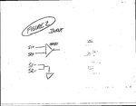
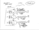
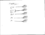
Hi, I am driving a coil at 10 kHz with a constant current source. There are two detector coils mounted axi-symmetrically positioned either side of the primary. All three coils have a resistance of 3 Ohms and inductance of about 275 uH (Figure 1). I am currently using foil shielded twisted pair cable for all three coils but I am having problems with noise when the cable is moved (presumably this is to do with the loop areas changing or changing coupling of the drive waveform into the secondary wires.) In the field, the cable is about 25m long and spliced to the shorter (1m) sensor cable but even in the lab with just the short sensor cable I notice a problem. I have a fairly simple input circuit (Figure 2) - the low side of the two secondary coils (S1- and S2-) are grounded and the high sides (S1+ and S2+) are fed into an instrumentation amplifier (AD621) - DC coupled. I didn't want to use coax because I was worried about having signals on the shields. The drive return (P-) is not grounded, it grounds through a sense resistor. And I was worried about running the S2- and S1- signals on the shields. But it occurred to me that I could use five coax cables (in one wire) in a scheme as shown in Figure 3. So, S1- and S2- are shorted close to the sensor and then ultimately connected to instrument common via the core conductor of Coax 2 in the figure. Would this give me better performance? Any other suggestions for wiring this system?
 

Attachments

  • Figure3.jpg
    Figure3.jpg
    277.4 KB · Views: 105
  • Figure2.jpg
    Figure2.jpg
    270.6 KB · Views: 113
  • Figure1.jpg
    Figure1.jpg
    494.6 KB · Views: 116

Earthing one side of your sensor cable is unbalancing the sensor cable. Just try with one cable with its "return" (now earthed) returned to the other input of the opamp. This should give you an added 60 db of pick up isolation due to the common mode rejection ratio of the opamp. Trouble is you now need 2 more op amps!
Frank
 

Using different coax lines for +ve and -ve signal causes arbitrary inductive coupling in the cable and might explain the instable signal when moving the cable. I guess that a single ended connection of sensor coils gives better performance. Of course shielded differential pairs as shown in the third picture would be the state-of-the-art cabling for this kind of transducers.

If you decide to send a differential dignal through separate single ended cables, the shield connection matters, too. Shorting the shields of a differential signal at both ends will considerably reduce the inductive coupling to external signals.
 

Hi,

I´d rely on shielded twisted pairs.
Use the same input impedance on both signals. (not grounding one and the other is high ohmic...)
Use appropriate input filters to get rid of HF.

If possible: Try to use an input impedance near your detector coils impedance.
(If your coils have about 10 k Ohms then use also 10 k Ohms at your signal amplifiers input. For sure this will make no sense with 0.1 Ohms impedance )
I know, this halfes the signal, but improves S/N ratio.

Btw: Is the useful signal from the detector coils modulated with the 10kHz excitation signal?
If so, you could do some "correlation like" filtering with the sensor signals. With that you get rid of all unwanted picked up noise and get very reliable values.

Is it possible to use signal transformers for the sensor signals?

Hope this helps
Klaus
 

....................
If possible: Try to use an input impedance near your detector coils impedance.
(If your coils have about 10 k Ohms then use also 10 k Ohms at your signal amplifiers input. For sure this will make no sense with 0.1 Ohms impedance )
I know, this halfes the signal, but improves S/N ratio.
........................
Why would matching the coil impedance improve the S/N ratio? It would seem you would want a high input impedance to maximize the signal voltage. Matching impedances does improve power transfer, but here we are interested in having the highest signal level to keep the signal as high above the induced noise as possible, not maximum power transfer.
 

Hi,

Matching impedances does improve power transfer,
I always thought that's the point. You get the maximum useful power. And all noise is a combination of voltage noise and current noise, means noise is not at its optimum...
Isn't then signal/noise at its optimum?

Noise critical amplifiers like satellite receivers also work with impedance matching.

.....at least this was my personal explanation of why one makes impedance matching...

Klaus
 

If the application is LVDT, resolver or something similar, there won't be particularly an impedance matching problem. Absolute signal level and SNR can be expected sufficient, but signal crosstalk and phase errors can considerably detoriate the sensor performance.
 

I always thought that's the point. You get the maximum useful power. And all noise is a combination of voltage noise and current noise, means noise is not at its optimum...
Isn't then signal/noise at its optimum?

Noise critical amplifiers like satellite receivers also work with impedance matching.
At high frequencies you need to use impedance matching to avoid reflections and standing waves in the transmission line connecting the two devices. It's not related to the noise level. If you are interested in generating maximum power from the signal then you indeed match the source impedance to the load (as they do in solar panel converters). But for low frequency, low level signals you typically want maximum voltage and aren't interested in maximum power transfer. For example audio circuits typically have a low impedance output and a high impedance input, even power amps. And certainly if you have external noise coupling in, then you want the maximum possible signal level.
 
Last edited:
  • Like
Reactions: FvM

    FvM

    Points: 2
    Helpful Answer Positive Rating
Hi,

at high frequencies you need to use impedance matching to avoid reflections and ...

for sure i know about terminating resistors...

what i meant is the impedance matching transformer between the input from antenna to the first transistor input stage ....
 

.................
what i meant is the impedance matching transformer between the input from antenna to the first transistor input stage ....
Well that is a case where you do want maximum power transfer between the low antenna impedance and the relatively higher transistor input impedance to give maximum signal voltage. But note, you are not changing the transistor input impedance to equal the antenna impedance (which is the change you originally suggested for the op's circuit) you are using a transformer to change the low impedance antenna voltage to match the first stage higher impedance. The transformer changes how you look at matching impedances.

You must be careful about using the maximum power transfer theorem. It only applies in limited applications (usually in the RF area).
 

Hi,

My ideas came from a linear technologies application note about noise calculations with opamp circuits. It was in times before the internet aera. The input generates voltage noise and current noise.... the conclusion of the application note was, the the best overall noise you get by using a source resistance that matches Unoise/Inoise. I know this u/i is not the input impedance...

If you have a source impedance of 50 Ohms and a input impedace of 20.000 ohms then the transformer ratio is sqrt(20000/50) = sqrt(400) = 20. One need a transformer with 1:20 to match impedance. No terminating resistance needed.
Yes,you are right, in my example i didn' t change antenna impedance and didn't change input impedance. I just matched it by using the appropriate transformer.

In a project i used a transformer to "match" a low resistance heating element with an H bridge output.
The heating element has an resistance of 0.1 Ohms and the bridge has a max output voltage of 40V and a limited current of 4A.
The bridge's max power output is at a load of 10 Ohms. (I know this is not the output impedance of the bridge...)
With a transformer of 10:1 one gets the max heating power.
What i want to say.. i know it is not "that known impedance matching" but the idea and the calculations are the same.

This is getting off topic...

The o.p. is free to try or not to try our suggestions. If he tries he will find out if our ideas will give a benefit.

I hope it helps..
Klaus
 

Thanks for all the replies. After digesting these thoughts and other discussions, I am wondering if what I actually need is a magnetic shield material as I am operating at such a low frequency (10 kHz)? Any comments? I did try the transformer coupling approach and it did not seem to help much although I do see the idea behind it. Thanks!
 

Status
Not open for further replies.

Similar threads

Part and Inventory Search

Welcome to EDABoard.com

Sponsor

Back
Top