Continue to Site

Welcome to EDAboard.com

Welcome to our site! EDAboard.com is an international Electronics Discussion Forum focused on EDA software, circuits, schematics, books, theory, papers, asic, pld, 8051, DSP, Network, RF, Analog Design, PCB, Service Manuals... and a whole lot more! To participate you need to register. Registration is free. Click here to register now.

Question about pn junction temperature characteristic

Status
Not open for further replies.

coolsummer

Junior Member level 3
Joined
Mar 18, 2019
Messages
28
Helped
0
Reputation
0
Reaction score
0
Trophy points
1
Activity points
477
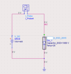
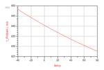
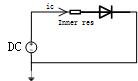
Hi all, we know that the pn junction voltage has a negative temperature coefficient. In my test bench, the diode is connected directly to the power supply, which is 3V. Temperature is the variable to sweep and the ic-temp curve is shown below. What puzzles me is: since the diode is connected directly to the power supply, the inner resistor of the diode plays a role, as temperature rises up, the junction voltage of the diode decreases, so the voltage across the inner resistor increases, and the currnet ic should also increase, but the simulation shows that ic decreases according to the temperature. What is wrong with my understanding?
 

Attachments

  • 1.png
    1.png
    24.8 KB · Views: 94
  • 2.png
    2.png
    6 KB · Views: 88
  • 3.jpg
    3.jpg
    2.4 KB · Views: 91

A diode is a diode and it does not have an inner resistor.
It will smoke then catch on fire if you connect it directly to the 3V power supply without limiting the current because its forward voltage is about only 0.7V.
Its forward voltage decreases if it heats, not its current which is controlled by whatever you use to limit its current.
 

Real diodes do have some internal parasitic resistance, but it is very small and will not limit to current to a safe value if you connect a voltage source directly to it.
You need to add an external resistance to limit the current to a low value and then measure the voltage across the diode (should be 0.6 to 0.7V at a few mA current).
 

It's pointless to discuss the problem without knowing details of the diode model.

If you apply 3V to a silicon diode, most of the voltage is dropped at the series (bulk) resistance.
 

What you are probing is a temperature dependence of a series resistance of the diode, this series resistance is increasing with temperature.

At the low level injection (i.e. low voltages, lower than ~0.7V for Si), when series resistance is not playing an important role, the current through the diode is determined by the diffusion, and is barrier limited - and increases with temperature, i.e. diode intrinsic resistance (it is nonliner, i.e. depends on voltage) is decreasing with temperature.
 

Your set-up is wrong..
If you want to see Temperature Dependency on Forward Voltage of the Diode, you should bias the Diode with a Constant Current Source.
Fix the Current then vary the Temperature then observe the Diode Drop-Out Voltage.
 

While constant current setup is more direct...
In the linear regime (i.e. if the variation of current or voltage versus temperature is small - and it is small, about 2% in this case) - the change of current with temperature (at constant voltage) is equal to the change of voltage (at constant current) - by absolute value - divided by differential resistance.
 

Is the diode still alive? with 3V across it and without any external series resistor?
 

Is the diode still alive? with 3V across it and without any external series resistor?
No problem, it's a simulation. The simulator doesn't complain about an useless simulation setup.
 

Status
Not open for further replies.

Similar threads

Part and Inventory Search

Welcome to EDABoard.com

Sponsor

Back
Top