tms8c8
Newbie level 4
I first have a general question about LDO and standard linear regulators: Does it hurt them to have a reverse current?
Second, instead of putting a schottky on the output of the LDO, can I use one at the input for the same effect, or is the current path from the output to ground (rather than output backfeeding Vin)?
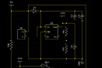
I have a little microcontroller system that normally runs from a 9V battery but occasionally has to drive a low impedance load for about 0.1 seconds. I use the internal resistance of the 9V battery as a current limiter to prevent damaging my low impedance circuit. However, I need my microcontroller (also powered by that same 9V battery) to remain on. Therefore, I have a schottky diode between the battery and Vin on an LDO regulator. I then have a large capacitance on Vin - large enough to keep Vin roughly 0.5 volt greater than Vout for up to 0.2 seconds (after which time, the low impedance load will be off and the voltage at the battery terminals will rise back up).
However, I would like to be able to tap into this using a USB cable. Right now, the LDO outputs 4.2V - high enough to run my little AVR at the desired frequency but low enough that my current draw is significantly less than if I ran at 5V. When I plug in the USB cable, the LDO is backfed with 5V - is this going to be a problem? Schematic of the power circuit attached.
(Basically I'm asking if I need to include another diode between Vout and the +5V port symbol in the schematic)
Thanks!

