Continue to Site

Welcome to EDAboard.com

Welcome to our site! EDAboard.com is an international Electronics Discussion Forum focused on EDA software, circuits, schematics, books, theory, papers, asic, pld, 8051, DSP, Network, RF, Analog Design, PCB, Service Manuals... and a whole lot more! To participate you need to register. Registration is free. Click here to register now.

Question about bypassing an LM386 circuit.

Status
Not open for further replies.

obrien135

Full Member level 5
Joined
Nov 10, 2009
Messages
240
Helped
5
Reputation
10
Reaction score
5
Trophy points
1,298
Location
Connecticut
Activity points
3,259
Hello again, annd thanks for all the help I have gotten so far. I have another question. The LM386 datasheet seems to indicate that it should be bypassed by a 10uF capacitor between pin 7 and ground. I don't have one, can I use a 4.7uF, or do Ihave to get a 10uF? The data sheet doesn't make it clear if it has to be a 10uF. It's a little vague about it.

George
 

It's there to prevent supply noise getting back into the earlier amplifier stages. A reduced value might give poorer performance but depending on circumstances you might get away with it. Don't forget that electrolytic capacitors often have values +/- 50% of that quoted so generally a wide tolerance of values would be accepted. The effect of a value too low would likely be instability and distortion at high volume levels.

Brian.
 
I meant to mention in the earlier message, that I am getting some clicking , or low frequency oscillation somewhere around or below 60Hz that seems to be coming from the LM386 circuit. Could this be caused by the wrong value bypass cap?
 

Hello again, annd thanks for all the help I have gotten so far. I have another question. The LM386 datasheet seems to indicate that it should be bypassed by a 10uF capacitor between pin 7 and ground. I don't have one, can I use a 4.7uF, or do Ihave to get a 10uF? The data sheet doesn't make it clear if it has to be a 10uF. It's a little vague about it.

George

When you analize the LM386's internal diagram you will find pin7 in the neighbourhood of resistances of 15k .. see attachment ..
Without going into details, anything above 1uF should perform well ..
Also, have a look at this application:
http://www.electronicecircuits.com/electronic-circuits/lm386-low-voltage-audio-power-amplifier
:wink:
IanP
 

Attachments

  • LM386internalcircuitschematic.png
    LM386internalcircuitschematic.png
    30.6 KB · Views: 105
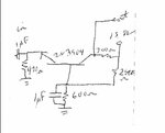
Perhaps I should start a new post for this question but it is related to the same problem. I will try posting it here, and see what happens. I added common base amp stage right before the lm386 stage and since then I have been getting that low frequency oscillation. How would the common base amp cause that? Or, it the oscillation is coming from the common base stage, would would I have done wrong in it's design to cause that to happen. A picture of the circuit is below.


George


common base.jpg
 
Last edited:

Although you don't show the full circuit, we can guess that insufficient supply bypassing of the preamplifier is causing the problem.

By the way, why di you choose a common base amplifier? It's very unusual for audio applications.
 
Thanks I will try to implement the supply bypassing. Would lack of this cause a buzz around 60 Hz? The reason I used the common base was that I was advised that it would provide better isolation of the load on the oscillator than the common collector buffer I have in there in front of it. Can I implement the bypassing for the whole unit (40M direct conversion receiver/ transmitter) at once or must it be done for each transister?

George


see the following for prior arrangement. The emittor follower is still there between the oscillator output and the common base amp.

**broken link removed**
 

That's an ugly circuit ! As I see it, you are feeding the output of a 7MHz oscillator into an LM386 then coupling an antenna to the oscillator to make it a direct conversion receiver. Not a good design.

With a few extra components you can make a proper mixer which will dramatically improve performance, you can then follow it with a simple LPF before the audio stages. Back to your original question though, there is no foermaula that will tell you how much decoupling is needed, the general rule is keep the supplies as clean as possible but your biggest leakage route will be the wiring method you have used. The commn base amplifier isn't the best for your application, you want a high imput impedance to minimize loading so an emitter follower will give better results. The drawback to using an emitter follower is no voltage gain so if you are prepared to compromise you can still use a 'normal' common emitter configuration. The best solution would be to use two stages, an emitter follower to prevent lading then a common emitter amplifier to give voltage gain. You really should try to keep RF out of the audio stages though.

Brian.
 
Thanks for the critique. I guess you are right. I tried putting bypassing and decoupling on the common base circuit since that is the one that seemed to introduce the problem. I didn't help. To put bypass and decoupling on all stages would be too messy at this point. And as you said the design isn't right so I'm going to scrap it. The lesson I seem to learn over and over again is: Don't be lazy about the decoupling early in the build. Maybe it will sink in this time. Thanks for all the help and advice. I do appreciate it.

George
 

If I was looking to build something like this, my thinking would be:

1. Tunable 7MHz Clapp oscillator.
2. Emitter follower after the oscillator to minimize loading.
3. After the emitter follower, a RX/RX switch.
4 (RX) to a single transistor mixer stage, LPF and then audio amp to a loudspeaker.
4 (TX) to a 2 stage power amplifier with the final stage having it's supply modulated to produce AM to the antenna.

Incidentally, the '3055 is useless as a power amplifier at 7 MHz, in fact it's pretty useless at 0.7MHz !!

I've got a nice ICOM IC-756 Pro 2 here though so other than for interest I won't be building a 7MHz band transceiver any day soon :)

Brian.
 
I got low-frequency oscillations (motorboating) with a similar audio op amp project, when my volume control (potentiometer) was set to low (or perhaps it was the middle range).

I could not figure out any reason for it. It sounded fine when I set it high.

I tried a few different resistor arrangements around the potentiometer. There was one where the motorboating did not occur. I never did figure out how my original resistor arrangement caused the oscillations to occur in the first place.
 
I tried putting a LPF on the input of the LM386 circuit because it seems like the LM386 keeps getting blown. When I added the filter, the chip didn't get hot any more but it might be already blown from before the filter was in there. Does the RF cause the chip to go bad? It seems like I am not getting gain through it anymore. It might be blown. Do you think that could be the case? I can't keep pouring money into the radio unecessarily. That is why I ask the question.

George

I changed the tip3055 to a faster one.
 
Last edited:

Show how you added the LPF. I would add a resistor (about 1K) in series with the audio and add a 1nF capacitor after it to ground. In a simple circuit like yours, it has to be a compromise between being too small to block the RF and too big to start muffling the high audio tones.

Yes, it is possible to damage most ICs by injecting RF in to them but it usually takes more power than a single transistor oscillator could provide. The damage is caused by the RF being rectified by the semicinductor junctions inside the IC and the resulting DC shift causing excess current to flow in the output stage.

For your output transistor, look for one with fT > 70MHz. The TIP3055 is specified as 2.5MHz.

Brian.
 
Yes, thank you. I used a 2n4401. I am having trouble with my scanner, but I'll get a picturee to you asap.

George

- - - Updated - - -

Here is a picture of the LPF:


For an audio filter that would (given the right values) be overkill. All you need to do is ensure nothing above say 20KHz gets into the amplifier. a simple RC filter would be more than adequate and eliminate the possibility of the LC circuit causing resonance problems when hooked up to the oscillator.

That's a huge jump from a TIP3055 to a 2N4401 but it should work much better.

Brian.
 

I don't know if you're allowed to ask on this forum, but would you want to sell the IC-756? If so, for what price?

George
 

Sorry George but it's not for sale.
I have a license to use it (GW6BWX) but primarily it get used as a test receiver. Having 30KHz to 60MHz coverage and a spectrum analyser built in makes it ideal for checking for EMC compliance and I have a down-converter feeding the second antenna input to extend the receive coverage up to 950MHz.

Brian.
 

AC line frequency (and harmonics) are notorious in DCR's, or so it seems. It turns out that it's NOT poor supply bypassing (try with a battery - the hum remains), but rather its due to poor LO isolation/ shielding !

LO which is at the same freq as the input signal leaks out, mixes with the AC power around the shack, and re-enters the RF input.

(paraphrased & ummaried from EMRFD revised 1st Edition pages 8.8 to 8.11)
 

Status
Not open for further replies.

Similar threads

Part and Inventory Search

Welcome to EDABoard.com

Sponsor

Back
Top