Continue to Site

Welcome to EDAboard.com

Welcome to our site! EDAboard.com is an international Electronics Discussion Forum focused on EDA software, circuits, schematics, books, theory, papers, asic, pld, 8051, DSP, Network, RF, Analog Design, PCB, Service Manuals... and a whole lot more! To participate you need to register. Registration is free. Click here to register now.

Question about antenna matching using a Balun

Status
Not open for further replies.

leszcz

Junior Member level 2
Joined
Aug 29, 2006
Messages
22
Helped
0
Reputation
0
Reaction score
0
Trophy points
1,281
Activity points
1,458
Hi,
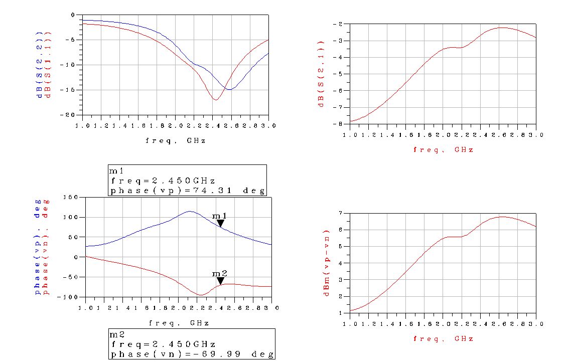
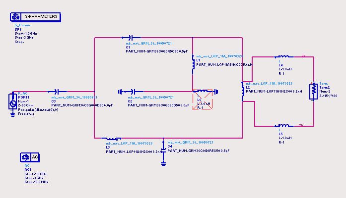
could someone pls explain me the way this balun is working ?
Can a balun be a matching circuit for the antenna at all or do I need additional 50ohm matching circuit ?

Thank u
 

Balun question

Without the passives values is more uncertain but...
C61&L62 = C81&L81 makes the +/- 90 deg shift of the balun.
C71 is DC block vs GND, its value is large.
L61 makes a matching on impedance vs IC
C62 makes a matching on impedance vs antenna

I hope it can help
Mazz
 

Re: Balun question

Here are the values , sry for that. U helped me a lot but im still not certain about antenna matching. If u had to match the antenna would u only change the C62 value ? Normally there is an inductance also needed for proper antenna match.
Why is actually L61 needed ? How is it working ?
Apart from that L62 is not equal L81 :(

Thank u
 

Balun question

Looking at values it seems that my assumptions (or sime of them) are wrong.
C71 is small, and I didn't noticed that the middle point is in TX/RX switch.
The circuit is more complex than I assumed to be.
Do you have other infos? Operating band?
IC data?

Mazz


May I argue 2.4~2.5 GHz?
 

Re: Balun question

yes its 2.4-2.5Ghz zigbee tranceiver, here is the manual, have a look at page 19 and 55, there is some description but very general.

**broken link removed**
 

Re: Balun question

Sorry for delay

I've done some simulations and I've got some results:
assuming that RF impedance is 115-J180 (complex cnj of optimum load impedance indicated in the datasheet), the balun shows a good in/out match but some unbalance (see difference between pos and neg phase that is less tha 180 deg), a couple of dB of insertion loss, a ratio of 1:4 (magnitude of input impedance is roughly 200 Ohm - in fact being 0 dBm the signal of the single ended port, we see roughly 6 dBm (voltage expressed in dBm) on differential voltage.

It is not clear to me why there is the TX/RX point connected inside the balun, maybe is for DC purpose, infact the connection point is unsensitive to high/low impedance (it is the C71 effect).

11_1170756226.jpg

17_1170756380.jpg
 

Status
Not open for further replies.

Part and Inventory Search

Welcome to EDABoard.com

Sponsor

Back
Top