Continue to Site

Welcome to EDAboard.com

Welcome to our site! EDAboard.com is an international Electronics Discussion Forum focused on EDA software, circuits, schematics, books, theory, papers, asic, pld, 8051, DSP, Network, RF, Analog Design, PCB, Service Manuals... and a whole lot more! To participate you need to register. Registration is free. Click here to register now.

QPSK Mod-Demod Simulink [Need Help]

Status
Not open for further replies.

Zhull

Newbie level 2
Joined
Oct 12, 2010
Messages
2
Helped
0
Reputation
0
Reaction score
0
Trophy points
1,281
Activity points
1,299
Hi everyone,

I'm currently simulating a (simple) QPSK mod/demod for my lab. project...

I *urgently* need your help for :
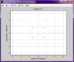
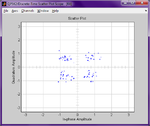
1. Is there any other way to make the received signal shown at RX's Discrete-Time Scatter Plot Scope to looks like TX's besides raising Eb/N0 rate at AWGN block? For example, adding more block or something?

2. Why the BER always show 0.5 (minimal)? Can we make it to 0? Because even if i remove the AWGN block and connecting QPSK Mod block directly to the Demod, the BER is not 0.

I'm open to any suggestion

PS: Sorry for my bad english.


QPSK.pngDTSP TX.pngDTSP RX.pngQPSK 2.png
 

Hi Zhull

1) Sorry, I don't understand your first question.

2) BER=0.5 does mean half of all bits in error.
May be you are not using differential encoding and TX and RX carriers are not absolutely synchronized. Use differential encoding/decoding.

Regards

Z
 

Thanks for your answer Zorro,

About my first question, as we can see, the constellation in RX's Discrete-Time Scatter Plot scope is scattered, now the task from my professor is what should i do to make it like four single dots (as we see in TX's)...i've tried to raise the Eb/N0 ratio in AWGN...and it works. But i'm asking, is there any other way for that?

And about BER, so i got to change the parameter in QPSK mod and Demod? Sorry, i'm a newbie in matlab/simulink

Here is the model...
View attachment QPSK2.rar
 
Last edited:

Hi Zhull,

it would be necessary to know what is inside the QPSK demodulator block.
For instance: Does it have a symbol synchronizer? That constellation could look like that because an misaligned symbol synchronization.
You could verify that placing a variable delay (from 0 to a symbol interval) in the signal path and see whether the constellation changes with the value of the delay.
Regards

Z
 
with a ber of 0.5 in qpsk with the received contellation as shown in the picture attached, I'd say you have messed up in the last two blocks.

It should not happen

let me get home, I'll correct the model for you.


---------------------------------------------------------
celebrating the civilization of my beloved Sindh this month
 

Status
Not open for further replies.

Part and Inventory Search

Welcome to EDABoard.com

Sponsor

Back
Top