Continue to Site

Welcome to EDAboard.com

Welcome to our site! EDAboard.com is an international Electronics Discussion Forum focused on EDA software, circuits, schematics, books, theory, papers, asic, pld, 8051, DSP, Network, RF, Analog Design, PCB, Service Manuals... and a whole lot more! To participate you need to register. Registration is free. Click here to register now.

[SOLVED] PWM output equation for 555 timer

Status
Not open for further replies.
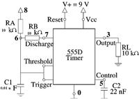
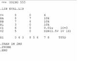
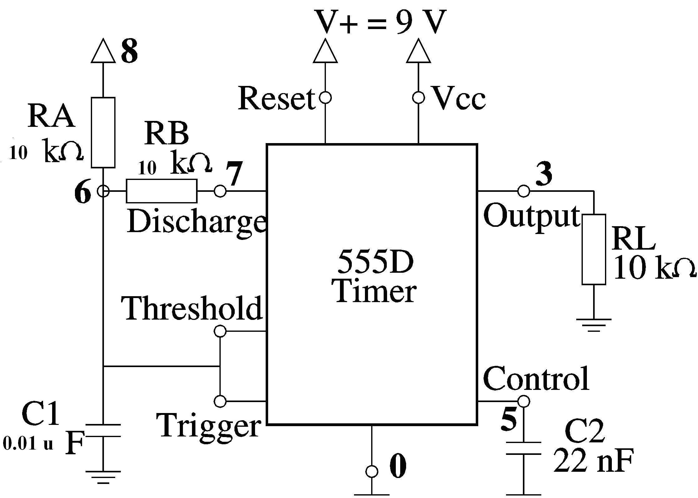
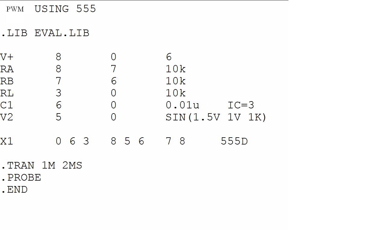
I used PSPICE for the folowing given circuit around the 555 timer IC to view the plot of PWM:


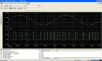
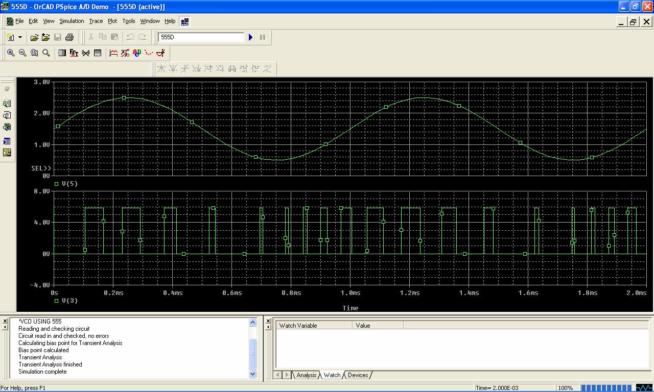
and got the following output.


The basic idea was to use the 555 as Astable multivibrator which was discussed in the following post:


the formulae i used:
t1= 0.693(RA+RB)C1----------charging cycle
t2= 0.693(RB)C------------------discharging cycle % Duty Cycle= t1/(t1+t2)
For the given combination following result was obtained;
% D= 66.66% frequency= 4.8kHz
 

how did you get this equation for C_tot and by the way practical supply voltage is 11.90 V.

---------- Post added at 12:50 ---------- Previous post was at 12:40 ----------

hi ashish,

the circuit you have posted , where is CV variations? That's what I want.
 

how did you get this equation for C_tot and by the way practical supply voltage is 11.90 V.

---------- Post added at 12:50 ---------- Previous post was at 12:40 ----------

hi ashish,

the circuit you have posted , where is CV variations? That's what I want.

As i mentioned that i used astable multivibrator circuit configuration and if you are aware of PSPICE coding then you can clearly see that i used pin no. 5 of 555 and fed the controlling voltage through it and the same is visible in the output. Ynu can see the difference between the outputs of this post and that of the post whose link i previously gave you.
Apart from this if you are still unsatisfied you can make your query more understandable to me.
 

Hi ashish,

I have the following doubts from your circuit.

1. The CV hast to vary from 1/3VCC to 2/3VCC, but I see in your circuit, sine wave varying much lower than 1/3VCC and still output is present.

2. What max freq can i feed to pin no.5 . What should be the corresponding R and C values.

3. By looking at your waveform of pulse width, I am unable to infer the instantaneous amplitude of the sine wave. This is my original question. Relation between pulse width and the magnitude of control voltage so that I can say that if I feed say 5 V, then I would get corresponding PWM output and so on.
 

So you couldn't consider replacing RA by a constant current source (using a pnp transistor for example).
As you know, the formula would be:
T = Vctl * C / I
Since I is constant T will be proporional to Vctl (in a limited range less than 0 to 12V as you will discover).

If even in this case T is different from the formula results (which is likely to happen) you will need to consider too the delays between:
Trigger -> output high
C at Vctl -> output low

Kerim
 

ya kerim

using constant current source, pwm is indeed linear. thanks
 

Status
Not open for further replies.

Similar threads

Part and Inventory Search

Welcome to EDABoard.com

Sponsor

Back
Top