Continue to Site

Welcome to EDAboard.com

Welcome to our site! EDAboard.com is an international Electronics Discussion Forum focused on EDA software, circuits, schematics, books, theory, papers, asic, pld, 8051, DSP, Network, RF, Analog Design, PCB, Service Manuals... and a whole lot more! To participate you need to register. Registration is free. Click here to register now.

Pure sinewave SPWM inverter

Status
Not open for further replies.
Temporarily short the inductor and observe if the output voltage increase.
 

i am wondering " that 181vdc at the input of the inverter generating only 20vac .
To diagnose this , first you make sure that the DC DC stage is working fine or not, so you can easily connect the 20 watt bulb and check the output voltage of DC DC stage , it should be 180vdc .
 

This sometimes happens when IR2110 is not connected properly.
 

I think the reason of getting only 20v AC is dc bus ( 180V).it will no longer be 180V at 20V AC output.so,before going to the next stages you have to improve your dc-dc converter.
 

i am wondering " that 181vdc at the input of the inverter generating only 20vac .
To diagnose this , first you make sure that the DC DC stage is working fine or not, so you can easily connect the 20 watt bulb and check the output voltage of DC DC stage , it should be 180vdc .

No it drops to 171Vdc with the 20W bulb but I assumed this was ok as the bulb is a resistive load hence there will be voltage drop. Also, the transformer no longer drops the voltage I think it was because I left out a air wire connect two grounds.

- - - Updated - - -

I think the reason of getting only 20v AC is dc bus ( 180V).it will no longer be 180V at 20V AC output.so,before going to the next stages you have to improve your dc-dc converter.

I checked the voltage while it is connected to h-bridge and I get 180Vdc just the same. when I test inverter with 12Vdc as the dc bus I get about 12VAC and when I vary the supply the ac output increases which is expected and so I am quite confused as to why with 180Vdc I am not getting over 100 VAC.
 

No it drops to 171Vdc with the 20W bulb but I assumed this was ok as the bulb is a resistive load hence there will be voltage drop. Also, the transformer no longer drops the voltage I think it was because I left out a air wire connect two grounds.

- - - Updated - - -


I checked the voltage while it is connected to h-bridge and I get 180Vdc just the same. when I test inverter with 12Vdc as the dc bus I get about 12VAC and when I vary the supply the ac output increases which is expected and so I am quite confused as to why with 180Vdc I am not getting over 100 VAC.


If my ferrite core max power is 321W in the dc-dc stage can I get a greater power by paralleling the push pull mosfets and would the transfomer be ok with???/
 

Would you consider doing something 'completely different', that is likely to involve more pain and will similarly be doomed to failure?

At the moment you are using a push-pull converter to generate a DC output bus for your full bridge and then using PWM, via a micro-controller, to gain some semblance of a sine wave.

Let's walk back to the battery.

Your push-pull converter is in effect a buck converter and as such it's input current, as drawn from the battery and assuming you do wish to achieve regulation rather than just putting power through the transformer, is discontinuous.

For example if you want 240W out from 12V in and your Push-Pull regulates at 80% duty cycle, 40% on time per switch, then you end up with a 0A/25A pull from the battery at the operating frequency of your controller.

Wet finger in the air says the battery will not like that and as a result you will be forced to include some form of input filtering.. It's also the case that your circuit layout will not like it as well.

You do not want to run multi-amp switched currents about the place unless you are prepared to keep them tight and local and in this case it is going to be hard to do. Having said as much no doubt others have experienced 'success', in varying degrees.

What to do?

First guess might be to implement a current fed push-pull boost converter..

https://www.ti.com/lit/ds/symlink/uc3827-1.pdf

Given I was forced to sign up for TI marketing dross I assume they will love the reference. No doubt TI is looking forward to 'up sell' or looking for 'bright ideas'.


You might wish to hunt elsewhere on the site for some of the application notes.. Otherwise conceptually you end up with one of these,

Screenshot from 2014-04-21 19:26:46.png

Your push-pull converter is now being, current fed, from a boost converter. The filtering inductor has been moved to the primary side, no need for the output inductor on the secondary side, and more importantly it is now in series with the battery.

As a result the battery no longer gets hammered with high frequency square amp currents and, assuming you keep things tight elsewhere, the pain might become less.

Of course you have now transferred that discontinuous current to the secondary side of the transformer but filtering becomes easier.

More pain later. You really do not wish to follow my floater.
 
Last edited:

Would you consider doing something 'completely different', that is likely to involve more pain and will similarly be doomed to failure?

At the moment you are using a push-pull converter to generate a DC output bus for your full bridge and then using PWM, via a micro-controller, to gain some semblance of a sine wave.

Let's walk back to the battery.

Your push-pull converter is in effect a buck converter and as such it's input current, as drawn from the battery and assuming you do wish to achieve regulation rather than just putting power through the transformer, is discontinuous.

For example if you want 240W out from 12V in and your Push-Pull regulates at 80% duty cycle, 40% on time per switch, then you end up with a 0A/25A pull from the battery at the operating frequency of your controller.

Wet finger in the air says the battery will not like that and as a result you will be forced to include some form of input filtering.. It's also the case that your circuit layout will not like it as well.

You do not want to run multi-amp switched currents about the place unless you are prepared to keep them tight and local and in this case it is going to be hard to do. Having said as much no doubt others have experienced 'success', in varying degrees.

What to do?

First guess might be to implement a current fed push-pull boost converter..

https://www.ti.com/lit/ds/symlink/uc3827-1.pdf

Given I was forced to sign up for TI marketing dross I assume they will love the reference. No doubt TI is looking forward to 'up sell' or looking for 'bright ideas'.


You might wish to hunt elsewhere on the site for some of the application notes.. Otherwise conceptually you end up with one of these,

View attachment 104497

Your push-pull converter is now being, current fed, from a boost converter. The filtering inductor has been moved to the primary side, no need for the output inductor on the secondary side, and more importantly it is now in series with the battery.

As a result the battery no longer gets hammered with high frequency square amp currents and, assuming you keep things tight elsewhere, the pain might become less.

Of course you have now transferred that discontinuous current to the secondary side of the transformer but filtering becomes easier.

More pain later. You really do not wish to follow my floater.

I am not sure I understand. So you're saying that I have been building a buck converter but if that were the case I would be getting less voltage at the output however I am getting a much higher voltage at the output than the input which is characteristic of a boost converter. I understand why you say buck converter because the inductor is at the output but the VOUT doesn't show this so I'm confused.

- - - Updated - - -

i am wondering " that 181vdc at the input of the inverter generating only 20vac .
To diagnose this , first you make sure that the DC DC stage is working fine or not, so you can easily connect the 20 watt bulb and check the output voltage of DC DC stage , it should be 180vdc .

BawA, ALERTLINKS or anyone else,

I am using the IRFZ44N MOsfet as the push pull and the datasheet says VGSth min=2V and max=4V so does that mean inorder to turn it fully on I should get more than 4V for VGS????

I just checked the VGS of the IRFZ44N and I get 0.36V for both lowside FETs with VDS=12V. Whats wrong here why am I getting such a small VGS??????????


PLease Help!!!!!!!!!!!!
 

I am not sure I understand. So you're saying that I have been building a buck converter but if that were the case I would be getting less voltage at the output however I am getting a much higher voltage at the output than the input which is characteristic of a boost converter. I understand why you say buck converter because the inductor is at the output but the VOUT doesn't show this so I'm confused.

- - - Updated - - -


BawA, ALERTLINKS or anyone else,

I am using the IRFZ44N MOsfet as the push pull and the datasheet says VGSth min=2V and max=4V so does that mean inorder to turn it fully on I should get more than 4V for VGS????

I just checked the VGS of the IRFZ44N and I get 0.36V for both lowside FETs with VDS=12V. Whats wrong here why am I getting such a small VGS??????????


PLease Help!!!!!!!!!!!!

What voltage should I get from the SG3525 OUTA and OUTB????? because these provide the gate drive for the IRFZ44N and so any voltage they output will be the same at the gate based on my tests.
 

I get 0.36V for both lowside FETs with VDS=12V.
If it would have been such a low value, there would have been no output, but you are getting 180V. You are not measuring it correctly. You can see 11V pulses with oscilloscope. You can observe 6V-8v with multilmeter depending on duty cycle because meter show only average.
 

Yes.. Your output voltage is higher but that's because of the transformer. Topologically it is still a Buck configuration. If you were to normalise what is on the secondary back to the primary you would find that the 'output' voltage is in fact less than the input voltage.

If I remember correctly you have a turns ratio of 3:80 for 180V out 180*3/80 = 6.75.. less than the input.

OK.. Ignore my flight of fantasy. Let's go back to yours and put a bit of thought into it. It looks like you are basing your ideas on,

https://tahmidmc.blogspot.co.uk/2013/01/using-sg3525-pwm-controller-explanation.html
https://www.blogger.com/profile/09117804893438710050

I believe the man concerned is a member of these forums.

First off consider your transformer,

https://tahmidmc.blogspot.co.uk/2012/12/ferrite-transformer-turns-calculation.html

Your solution apparently uses an ETD34 core with three turns on the primaries. Here's a ferrite core databook.

https://www.epcos.com/blob/519704/download/2/ferrites-and-accessories-data-book-130501.pdf

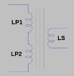
Ignore all that for the moment.. Here's what your transformer looks like,

Screenshot from 2014-04-22 08:24:32.png

Those 'inductors' are real. The technical term for them is magnetising inductance. Individually your windings are in fact inductors. The core might serve to couple them together but nonetheless they behave like inductors.

Some sums.

L = Uo.Ue.N².Ae/Le

Uo permeability of free space.
Ue effective permeability of your core.
N number of turns.
Ae effective area of your core.
Le effective magnetic path length of your core.

B = Uo.Ue.N.I/Le

I is the current in the winding.

Bear in mind that these are SI units..

Re-arrange those..

Uo.Ue = N².Ae/L.Le
Uo.Ue = N.I/B.Le

Equate

N².Ae/L.Le = N.I/B.Le

Re-arrange and cancel some things

N = L.I/B.Ae

Now if you wanted to design an inductor of value L to carry a maximum current of Ipk with a maximum flux of Bpk then given the effective area of your core you can work out the minimum number of turns you require. It gets a bit more complicated in that you also have to consider winding losses. There is a sum that can be derived to give you a first cut as a guess...

For the moment we are looking at transformers. In particular for a Switch Mode Power Supply which in this case is imposing square wave voltages across the windings. As before realise that these windings are in fact inductors. If you apply a voltage across an inductor then the current through it ramps up over time.

I = Vin.T/L

In the transformer we say that the primary magnetising inductance is 'set' during the switch on time, Ton. I'll ignore 'reset' for the moment but just assume it goes back to zero during the switch off time. Peak current in the magnetising inductance is therefore..

Ipk = Vin.Ton/L

Re-writing the second to last one..

N = L.Ipk/Bpk.Ae

Re-arrange

Ipk = N.Bpk.Ae/L

Equating

Vin.Ton/L = N.Bpk.Ae/L

Re-arrange

N = Vin.Ton/Bpk.Ae

This lets you calculate the required number of primary turns to achieve a target value for Bpk. In your converter assuming you have set up the SG3525 to switch at 100KHz the maximum switch on time is 10uS.. 1/Fs. Your maximum input voltage is something like 13.4V for a lead acid battery.

Screenshot from 2014-04-22 09:27:55.png

For the ETD34 Ae is 97.1mm²

Ferrite comes in various flavours. For power conversion you will be looking to use things like N27/N87, other manufacturers will use different names. For the moment,

Screenshot from 2014-04-22 09:32:44.png

In terms of saturation they are much of a muchness and wet finger suggests you pick a Bpk of 300mT. Things are more complex because you have to consider core losses and you have the added {dis}advantage that your push-pull converter operates in both quadrants along with other possible problems.

For the moment we'll pick 300mT and put them all together to get

Np = 13.4*10E-6/0.3*97E-6

Np = 4.6

Round up to 5

Tahmid's equation is visually more complex since he uses f instead of Ton, 1/f, and he is using Gauss rather than the SI unit of Tesla for flux so there is an extra 'fiddle factor' involved.

https://tahmidmc.blogspot.co.uk/2012/12/ferrite-transformer-turns-calculation.html

There is one other problem with it but do not quote me on this one. I'm fairly sure that the form of his equation is actually used for low frequency mains transformers where the drive voltage is sinusoidal rather than being a square wave. Happy to be corrected though.

Back to the Ferrite data book

Screenshot from 2014-04-22 09:59:11.png

They quote Al values for ungapped cores. This is Specific Inductance Per Root Turn.. Previously,

L = Uo.Ue.N².Ae/Le

Al = Uo.Ue.Ae/Le

L = Al.N²

You can therefore calculate what your primary magnetising inductance is. In this case,

Lp = 2200E-9*5²
Lp = 55uH

Ipk = Vin.Ton/L
Ipk = 13.4*10E-6/55E-6
Ipk = 2.44A

The switches/windings and, battery, source have to carry this current in addition to the reflected secondary current.

That's enough for now.

Hopefully you can have a read through it and make sense of it. It is correct but things will by their nature become more complex. I do not know it all but magnetics design is a 'complex' subject and whilst there appear to be 'magic sums' available it is probable that you will find you have to 'iterate' towards a particular goal.
 
Let's do the voltage mode control 'deal breaker'.

In as much as the primary magnetising inductance gets set during switch on time it has to be reset during switch off time. In the case off your push-pull converter one switch drives it one way and then the other switch drives it the other way.

Here is your push-pull converter with 'dots' on. In some long ago collection of notes, possibly/probably from Linear Technology the advice was something along the lines that those dots do not represent 'smashed flies'.

Screenshot from 2014-04-22 13:50:42.png

With S1 on you are in effect applying a negative voltage to the 'smashed fly' end of LP1. Given the 'smashed fly' end of LP2 is fixed at VBATT the other end goes positive imposing twice the voltage on S2 which is off. It's the reason why switches in push-pull converters have to be rated at at least twice the input supply voltage before you consider other things.

With S1 on it carries both the reflected secondary current and the current due to the magnetising inductance. Ignoring the reflected current that due to the magnetising inductance ramps up. Then your switches swap over. S2 is now carrying the reflected secondary current and that due to the magnetising inductance.. but its 'smashed fly' is applying the opposite voltage to the magnetising inductance so that ramps down.

There is this thing called a 'volt-second' balance.

If the volt-seconds applied to the magnetising inductance by S1 and S2 are equal then the 'average' current in the magnetising inductance sits at a given level and things are good..

dIS1 = Vin.TSW1/Lmag
dIS2 = Vin.TSW2/Lmag

Tsw1 = Tsw2 = Good
Tsw1 /= Tsw2 = Flux walking = Transformer Saturation = Hot Broken Things = Bad

Voltage mode control pays no attention to the possibility of differentials in the switch on times and therefore things are likely to snuff themselves.. unless you are lucky.
 

Yes.. Your output voltage is higher but that's because of the transformer. Topologically it is still a Buck configuration. If you were to normalise what is on the secondary back to the primary you would find that the 'output' voltage is in fact less than the input voltage.

If I remember correctly you have a turns ratio of 3:80 for 180V out 180*3/80 = 6.75.. less than the input.

OK.. Ignore my flight of fantasy. Let's go back to yours and put a bit of thought into it. It looks like you are basing your ideas on,

https://tahmidmc.blogspot.co.uk/2013/01/using-sg3525-pwm-controller-explanation.html
https://www.blogger.com/profile/09117804893438710050

I believe the man concerned is a member of these forums.

First off consider your transformer,

https://tahmidmc.blogspot.co.uk/2012/12/ferrite-transformer-turns-calculation.html

Your solution apparently uses an ETD34 core with three turns on the primaries. Here's a ferrite core databook.

https://www.epcos.com/blob/519704/download/2/ferrites-and-accessories-data-book-130501.pdf

Ignore all that for the moment.. Here's what your transformer looks like,

View attachment 104524

Those 'inductors' are real. The technical term for them is magnetising inductance. Individually your windings are in fact inductors. The core might serve to couple them together but nonetheless they behave like inductors.

Some sums.

L = Uo.Ue.N².Ae/Le

Uo permeability of free space.
Ue effective permeability of your core.
N number of turns.
Ae effective area of your core.
Le effective magnetic path length of your core.

B = Uo.Ue.N.I/Le

I is the current in the winding.

Bear in mind that these are SI units..

Re-arrange those..

Uo.Ue = N².Ae/L.Le
Uo.Ue = N.I/B.Le

Equate

N².Ae/L.Le = N.I/B.Le

Re-arrange and cancel some things

N = L.I/B.Ae

Now if you wanted to design an inductor of value L to carry a maximum current of Ipk with a maximum flux of Bpk then given the effective area of your core you can work out the minimum number of turns you require. It gets a bit more complicated in that you also have to consider winding losses. There is a sum that can be derived to give you a first cut as a guess...

For the moment we are looking at transformers. In particular for a Switch Mode Power Supply which in this case is imposing square wave voltages across the windings. As before realise that these windings are in fact inductors. If you apply a voltage across an inductor then the current through it ramps up over time.

I = Vin.T/L

In the transformer we say that the primary magnetising inductance is 'set' during the switch on time, Ton. I'll ignore 'reset' for the moment but just assume it goes back to zero during the switch off time. Peak current in the magnetising inductance is therefore..

Ipk = Vin.Ton/L

Re-writing the second to last one..

N = L.Ipk/Bpk.Ae

Re-arrange

Ipk = N.Bpk.Ae/L

Equating

Vin.Ton/L = N.Bpk.Ae/L

Re-arrange

N = Vin.Ton/Bpk.Ae

This lets you calculate the required number of primary turns to achieve a target value for Bpk. In your converter assuming you have set up the SG3525 to switch at 100KHz the maximum switch on time is 10uS.. 1/Fs. Your maximum input voltage is something like 13.4V for a lead acid battery.

View attachment 104519

For the ETD34 Ae is 97.1mm²

Ferrite comes in various flavours. For power conversion you will be looking to use things like N27/N87, other manufacturers will use different names. For the moment,

View attachment 104521

In terms of saturation they are much of a muchness and wet finger suggests you pick a Bpk of 300mT. Things are more complex because you have to consider core losses and you have the added {dis}advantage that your push-pull converter operates in both quadrants along with other possible problems.

For the moment we'll pick 300mT and put them all together to get

Np = 13.4*10E-6/0.3*97E-6

Np = 4.6

Round up to 5

Tahmid's equation is visually more complex since he uses f instead of Ton, 1/f, and he is using Gauss rather than the SI unit of Tesla for flux so there is an extra 'fiddle factor' involved.

https://tahmidmc.blogspot.co.uk/2012/12/ferrite-transformer-turns-calculation.html

There is one other problem with it but do not quote me on this one. I'm fairly sure that the form of his equation is actually used for low frequency mains transformers where the drive voltage is sinusoidal rather than being a square wave. Happy to be corrected though.

Back to the Ferrite data book

View attachment 104523

They quote Al values for ungapped cores. This is Specific Inductance Per Root Turn.. Previously,

L = Uo.Ue.N².Ae/Le

Al = Uo.Ue.Ae/Le

L = Al.N²

You can therefore calculate what your primary magnetising inductance is. In this case,

Lp = 2200E-9*5²
Lp = 55uH

Ipk = Vin.Ton/L
Ipk = 13.4*10E-6/55E-6
Ipk = 2.44A

The switches/windings and, battery, source have to carry this current in addition to the reflected secondary current.

That's enough for now.

Hopefully you can have a read through it and make sense of it. It is correct but things will by their nature become more complex. I do not know it all but magnetics design is a 'complex' subject and whilst there appear to be 'magic sums' available it is probable that you will find you have to 'iterate' towards a particular goal.

ok the ferrite core I am using is from Jameco electronics part #:2160665 it is not a ETD34 I just matched the specs and they have the same max power of 321W so I based the turns off the ETD34 since jameco did not give the Ac hich is the cross sectional area.
 

If SPWM is used, without LC-filter, output should be 20KHz pulse train modulated with 50Hz AC . It should deliver full current even with 12V supply. Use a car-12V bulb as load and see if it lights bright, FETs don't heat-up too much and there is no DC offset on either side.

Note that if a 12V pulse train of 50% duty cycle is observed with muti-meter, it will show averaged voltage i.e. near 6V. Peak voltage can be observed with an oscilloscope after calibration.

As output is AC, non-polar capacitor is required.

ALERTLINKS or any one else,

I used a 12V 5W car light at the output of the inverter and the bulb lights up but the voltage drops to 7V-AC and the FETs do not heat up and I used a 12V 17Ah battery at the input. I know the bulb is a resistive load so there will be a voltage drop. Also, without a load I get 12V-AC at output of h-bridge with 12V dc from battery as the dc bus to h-bridge. Should I be getting this result ????
 

may be the bootstrap capacitor is not enough to keep the mosfet ON for entire 10ms duration . what is the carrier frequency of spwm and the value of bootstrap capacitor ?
 

ok the ferrite core I am using is from Jameco electronics part #:2160665 it is not a ETD34 I just matched the specs and they have the same max power of 321W so I based the turns off the ETD34 since jameco did not give the Ac hich is the cross sectional area.

http://www.jameco.com/webapp/wcs/stores/servlet/Product_10001_10001_2160665_-1

Jameco give "Manufacturer no. PC40HEER35-Z" PC40 is a TDK core material and EER35 looks like the core shape.

Unfortunately it looks like the product has been deprecated by TDK so best guess would be Jameco are selling end of line product or a version from a different manufacturer. You will have to trust that Jameco is providing you with what they claim is a TDK core or direct equivalent.

Core material properties, loss curves for PC40 and others, are available from here,

http://www.tdk.co.jp/tefe02/e16_1.pdf

Core information is available from here,

**broken link removed**

The above also kindly provides you with some useful temperature rise versus total loss, windings plus core, curves.

Bobbin information available from here,

**broken link removed**

It might take a bit of time to extract meaningful dimensions from the last one... I'm kind of guessing that since Jameco don't appear to sell bobbins you do not have one?

Otherwise.. yes it does look like what you have is similar to the ETD34 but now you have a complete set of data to work from.

I wouldn't recommend believing 'headline' figures for power throughput. They rely on a number of unstated factors. You can get some idea about how fanciful they might be based on..

Screenshot from 2014-04-23 09:27:20.png

Note they are claiming 325W @ 100KHz whilst they give core losses of 4.2W @ 200mT|100KHz. Now look at the bottom right graph. That's for 'Total Loss', core and winding.

If you were to assume equal core and winding losses of 4.2W then the total would be 8.4W and, if you extrapolate the line, then you are looking at a 120°C rise above ambient.

Place it in a box at 50°C and your transformer will be sitting at 170°C or higher. Obviously to achieve their headline figure they are using forced cooling.

I've got to go shopping. We'll try some sums later.
 

It is later. Shopping done. Let's do sums.

Bear in mind that this is a methodology and you can vary it according to your own requirements and goals. I'm going to base this on convection cooling whereas the 'headline' figure suggests the manufacturers have chosen to give a figure for forced air cooling without providing further data. Forced air cooling is another layer of complexity...

From,

**broken link removed**

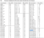
Screenshot from 2014-04-23 14:19:22.png

I guess one problem here is that they identify a measurement point but do not indicate whether it is a surface point or a point within the centre of the windings. Assume they have buried their thermocouple in the windings to get a 'worse case' figure.

You might use the graph directly to read numbers but you can convert what it is saying into a thermal resistance figure, Rth. 3W total dissipation gives you a 50°C rise which becomes roughly 17°C/W

For a quick 'reality check', assuming there is such a thing as reality in this game, the EPCOS{TDK} data book linked to previously gives a value of...

Screenshot from 2014-04-23 12:38:54.png

20°C/W Grumble grumble. They are not a 'million miles' out and just above the ETD34 value an ER35/20/11 is quoted at 18°C/W. We'll run with TDK's 17°C/W.

In the world of hard and fast rules as applied to magnetics design there are no hard and fast rules.. just starting points in order to move towards a solution. First one is you assign equal losses to the core and the windings. Pick an ambient temperature of 50°C and guess how hot you want your transformer to get.

The limiting factor in terms of temperature is likely to be the sort of inter winding insulation tape you will have access to or wish to use. Generally you will be using the 'yellow' polyester stuff with 'rubber' adhesive. I'll fail to go the extra mile and just say it is 'good' to 120°C operating temperature.

Given 50°C ambient and 120°C hotspot your permissible temperature rise is 70°C. Take the previous 17°C/W and 70/17 gives you a total, core plus winding, loss of 4.1W. Split that between core and windings and call it 2W core with 2W windings.

Given your core is, supposedly, PC40 ferrite then..

http://www.tdk.co.jp/tefe02/e16_1.pdf

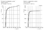
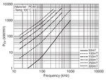
Screenshot from 2014-04-23 13:07:42.png

I'm being 'Mr Dangerous' here and using the 100°C figures on the assumption that the core is in effect actually going to operate at a lower temperature than the windings given it is more exposed to the external environment and its insides will be more tightly 'coupled' to its outsides in order to move internal heat away.

You might wish to check what happens either side in terms of increased or decreased losses based on operating temperature.

The graph gives Pv as kW/m³

Elsewhere for your core,

**broken link removed**

Screenshot from 2014-04-23 13:24:33.png

The Effective Volume, Ve, of the core is given as 9720mm³ so there will be a bit of a 'conversion fiddle' that has to be applied.

Going for another 'reality check' as noted previously TDK claim 4.2W core loss when operating with a flux excursion of 200mT at 100KHz. Let's see how that one might work.

From the graph 200mT @ 100KHz gives about 400kW/m³. Take 9720mm³ and convert it to m³... 9720E-9 multiply and the result is 3.9W. The 'science' is not exact but once again it is in 'the ball park'. If you look back at the graph for core loss you will see my 'guess' of 400 was slightly low.

Turning things around our target is 2W core loss from 9720mm³ so dividing, 2/9720E-9 sticks us at a Pv of about 200kW/m³. Your transformer is working at a frequency of 50KHz so going back to the graph.. we end up being bounded between the 200mT and 250mT curves.

I have to admit to being a failure here because I have not worked out how to interpolate between lines on what appears to be a logarithmic dependency. However in order to wimp out I notice that 60KHz @ 200mT hits the 200kW/m³ spot.

This becomes your operating peak flux with a switching frequency, Fs, of 120KHz. Switch on time is , 1/Fs, 8.3uS. Bpk is 200mT. Effective area, Ae.. you refer to it as AC, is 107mm². Vin, possibly my mistake, is 13.4V

Npmin = Vin.Ton/Bpk.Ae
Npmin = 13.4.8.3E-6/200E-3.107E-6
Npmin = 5.2

Call it 5.

Things will fall to pieces later. They generally do.
 
Last edited:

may be the bootstrap capacitor is not enough to keep the mosfet ON for entire 10ms duration . what is the carrier frequency of spwm and the value of bootstrap capacitor ?
I am using the atmega32 so the carrier frequency is 8000Hz and the boot strap cap is a 47uF, 25V.Should I use the atmega16 instead with a switching frequency of 16000Hz??

- - - Updated - - -

It is later. Shopping done. Let's do sums.

Bear in mind that this is a methodology and you can vary it according to your own requirements and goals. I'm going to base this on convection cooling whereas the 'headline' figure suggests the manufacturers have chosen to give a figure for forced air cooling without providing further data. Forced air cooling is another layer of complexity...

From,

**broken link removed**

View attachment 104588

I guess one problem here is that they identify a measurement point but do not indicate whether it is a surface point or a point within the centre of the windings. Assume they have buried their thermocouple in the windings to get a 'worse case' figure.

You might use the graph directly to read numbers but you can convert what it is saying into a thermal resistance figure, Rth. 3W total dissipation gives you a 50°C rise which becomes roughly 17°C/W

For a quick 'reality check', assuming there is such a thing as reality in this game, the EPCOS{TDK} data book linked to previously gives a value of...

View attachment 104589

20°C/W Grumble grumble. They are not a 'million miles' out and just above the ETD34 value an ER35/20/11 is quoted at 18°C/W. We'll run with TDK's 17°C/W.

In the world of hard and fast rules as applied to magnetics design there are no hard and fast rules.. just starting points in order to move towards a solution. First one is you assign equal losses to the core and the windings. Pick an ambient temperature of 50°C and guess how hot you want your transformer to get.

The limiting factor in terms of temperature is likely to be the sort of inter winding insulation tape you will have access to or wish to use. Generally you will be using the 'yellow' polyester stuff with 'rubber' adhesive. I'll fail to go the extra mile and just say it is 'good' to 120°C operating temperature.

Given 50°C ambient and 120°C hotspot your permissible temperature rise is 70°C. Take the previous 17°C/W and 70/17 gives you a total, core plus winding, loss of 4.1W. Split that between core and windings and call it 2W core with 2W windings.

Given your core is, supposedly, PC40 ferrite then..

http://www.tdk.co.jp/tefe02/e16_1.pdf

View attachment 104580

I'm being 'Mr Dangerous' here and using the 100°C figures on the assumption that the core is in effect actually going to operate at a lower temperature than the windings given it is more exposed to the external environment and its insides will be more tightly 'coupled' to its outsides in order to move internal heat away.

You might wish to check what happens either side in terms of increased or decreased losses based on operating temperature.

The graph gives Pv as kW/m³

Elsewhere for your core,

**broken link removed**

View attachment 104583

The Effective Volume, Ve, of the core is given as 9720mm³ so there will be a bit of a 'conversion fiddle' that has to be applied.

Going for another 'reality check' as noted previously TDK claim 4.2W core loss when operating with a flux excursion of 200mT at 100KHz. Let's see how that one might work.

From the graph 200mT @ 100KHz gives about 400kW/m³. Take 9720mm³ and convert it to m³... 9720E-9 multiply and the result is 3.9W. The 'science' is not exact but once again it is in 'the ball park'. If you look back at the graph for core loss you will see my 'guess' of 400 was slightly low.

Turning things around our target is 2W core loss from 9720mm³ so dividing, 2/9720E-9 sticks us at a Pv of about 200kW/m³. Your transformer is working at a frequency of 50KHz so going back to the graph.. we end up being bounded between the 200mT and 250mT curves.

I have to admit to being a failure here because I have not worked out how to interpolate between lines on what appears to be a logarithmic dependency. However in order to wimp out I notice that 60KHz @ 200mT hits the 200kW/m³ spot.

This becomes your operating peak flux with a switching frequency, Fs, of 120KHz. Switch on time is , 1/Fs, 8.3uS. Bpk is 200mT. Effective area, Ae.. you refer to it as AC, is 107mm². Vin, possibly my mistake, is 13.4V

Npmin = Vin.Ton/Bpk.Ae
Npmin = 13.4.8.3E-6/200E-3.107E-6
Npmin = 5.2

Call it 5.

Things will fall to pieces later. They generally do.

Can you calculate the Nsec for me please time is against me. So your'e saying I need 5 turns on pri at 50KHz in order to get about 180Vdc at the output of dc-dc converter??? Ok so the Ae for ETD34 is 97.1mm² and for the core from jameco the Ae or Ac=107mm² right?

If thats the case I used 4 turns on the pri and 80 on the secondary

For 107mm² using the eqn Tahmid used I still get 4 turns on pri help me out here with both pri and sec for 107mm² please..
 
Last edited:

may be the bootstrap capacitor is not enough to keep the mosfet ON for entire 10ms duration . what is the carrier frequency of spwm and the value of bootstrap capacitor ?

From my power supply when I measure the current I am getting 0.1A at 12V and at the dc-dc converter stage I am getting 180Vdc at 0.1A therfore I guess thats why it the dc-dc converter can only light up a 20W bulb since 180V x 0.1A= 18W and the 20W bulb drops the 180Vdc to about 165-170Vdc when I connect the 180Vdc to the h-bridge I get about 24V-AC from a 14.7Vdc from power supply.

So do I just need to increase the input power in order to get the 110 or 120V-AC?????
When I used 12V as the dc bus for the h-bridge I got 12V-AC and when I connect a transformer at the output of the h-bridge I get 109V-AC when I removed the transformer and tested with a 12V , 21W car bulb it lit up but not fully and it also pulled down the voltage but I understand why that happened because the power is very low.
 
Last edited:

Morning. Back again. Returning to,

**broken link removed**

It's a bit difficult to separate out which bobbin is which but using minimum figures the available winding width, Ww, is C 26mm. The available winding height is (A-B)/2 or about 5.8mm.

We'll assume you are going to use 3mm margins either end for insulation. That reduces your winding width to 20mm. With 5 turns per primary and assuming you wind them side by side in one layer that is 10 turns total so each wire will have 2mm available to it.

That's going to cause problems with skin effect, you also have to worry about proximity effect...

http://www.ti.com/lit/ml/slup125/slup125.pdf

There is probably more comprehensive information available from elsewhere but the above gives you some idea as to what is going on. Otherwise you can 'cheat'.

**broken link removed**

Software here,

www.genomerics.talktalk.net/software/roundwire/roundwire.zip

It was written in Delphi 4 and might fall over on newer versions of Windows latest operating systems. Should be fine under XP. You can see the underlying code in the roundedit.pas file which should be viewable in a text editor.

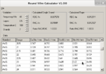
Available wire width is 2mm so make that up as a twisted rope of 7 strands. The overall diameter will be three times the wire diameter so your wire is 2/3 or 0.66mm.

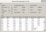
Screenshot from 2014-04-24 05:59:56.png

You can see in the above that AWG23 is selected. Insulated wire diameter is 0.63mm. L,S,H and T refer to the insulation thickness. Light, Single, Heavy and Thick. For 'high' voltage SMPS work you will generally be using Heavy.

The other stuff..

Top left are the input variables. Frequency is 60KHz which is your new transformer switching frequency. You IC clock will be at 120KHz. Layers deals with proximity or layer effect. In this case it is set to 0.5 because we are going to sandwich the primaries between the secondary, secondary wound in two sections. Temperature is your expected maximum transformer operating temperature. Strands, as per the above, is set to 7.

Calculated values, Single strand and Rope appear top middle and top right. DC and AC resistances per metre and the ratio. You cannot do better than 1 for the ratio and 1.5 is sometimes suggested as a 'target'. In this case the solution looks like a good one which is sort of unusual because you often find things do not fit together so well and you have to consider different solutions.

The bobbin data gives a value for the Mean Length of a Turn, MLT,

Screenshot from 2014-04-24 06:22:50.png

60.8mm for the EER35. With 5 turns on the primary the winding length will be 5*60.8 or 0.304m so RDC = 0.0038R and RAC = 0.0039R. That ignores lead outs.

Previously we allowed for 2W core loss and 2W winding loss. Split the 2W winding loss between primaries and secondary and that gives 1W each. Then split that 1W for the primary between them for 0.5W each.

Without being rigorous assuming a 50% duty cycle current square pulse the RMS value is,

Irms = A.√ D = 0.7071 * A

Given the RAC/RDC ratio is one the whole wire will be utilised and we need not consider the DC or AC components but rather use the above as an absolute figure. Given RDC = 0.0038R for a loss of 0.5W the permissible RMS current is √(0.5/0.0038) or 11.5A giving an amplitude of 16A which will be the current draw from the battery.

Assuming the nominal battery voltage is 12V then the maximum power throughput for this transformer will be 192W.

Your burning question was how many secondary turns?

Given the end discharge voltage of a loaded lead acid battery is 10.5V

http://www.farnell.com/datasheets/19849.pdf

Screenshot from 2014-04-24 07:35:13.png

With a desired Fclk of 120KHz the period is 8.333uS. Choose a discharge time of 1uS, right graph. This will be the 'dead time'. CT = 1nF RD = 150R. The remainder, 7.333uS becomes the charge time, left graph, which makes RT = 9K1. Maximum duty cycle is 7.33/8.33 or 88%

With a minimum input voltage of 10.5V the average at the transformer primary will be 0.88*10.5 = 9.24V You want 180V out so the required turns ratio is 180/9.24 or 19.48 which based on the 5 turn primaries makes the required number of secondary turns 97.4 so choose 100.

As before your available bobbin winding width after margins is 20mm. We'll do the secondary as two sections with two layers of 25 turns per layer sandwiching the primaries. Available width for the wire is 20/25 or 0.8mm. Again we use a rope but this time 7 strands of something close to 0.8/3 or 0.2667mm overall diameter.

Screenshot from 2014-04-24 08:35:08.png

AWG31 fits the bill. Rope diameter will be 0.792 which, 25 turns, will fit the available winding width. The height for 4 layers will be 3.168mm and our primary occupied 1.89mm giving a total height for the windings alone of 5.058mm less than the available winding height of 5.8mm. That leaves adequate space for inter winding insulation.

You will end up with a 'power bulge' across the top of the bobbin as a result of the primary lead outs.

Again RAC/RDC is close to one with RDC = 0.080705 and RAC = 0.085073 MLT is 60.8mm so length of the secondary is about 6 metres giving RDC ~ RAC = 0.52R. This time secondary current approximates to a true square wave which is entirely composed of AC harmonics.

Irms = A

Given our limit on dissipation was set to 1W for the secondary A works out to be √1/0.52 or 1.39A. For the 180V out that's 250W. The numbers never match because you are dealing with discrete sizes of wire and have to fit them in to the available dimensions.

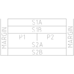
It's not very explicit but this represents the winding structure for your transformer.

transformer.png

Now then.... about this 'voltage mode control' and flux walking. Whilst 'time is of the essence', smells like a final year project, would you at least consider using 'current mode control' instead? Assuming you do things right life, for this part at least, will become less stressful..

http://www2.microsemi.com/document-portal/doc_download/11139-sg1846-pdf

Screenshot from 2014-04-24 09:11:11.png

Looks similar but different.
 

Status
Not open for further replies.

Similar threads

Part and Inventory Search

Welcome to EDABoard.com

Sponsor

Back
Top