rehakmatej
Newbie level 4
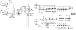
Hello, I have a pure sine wave inverter whose schematic is in picture bellow (values of filter inductors TL1 and TL2 is 27 uH and filter cap is 4.7 uF behind both inductors). output is connected to resistive load.

The sinusoidal PWM is generated by MCU whose duty cycle and final sine wave voltage level can be adjusted by potentiometer (switching frequency of SPWM is 40 kHz). My problem is that, when the duty cycle on the top of sine wave is less than about 50 %, the sine wave looks fine as described in picture bellow:

When the duty cycle on the top of sine wave is about 50 - 60 %, the top of sine wave is distorted into "flat" shape as described in the picture bellow:

And when the duty cycle is greater than about 60%, there is strange "step" on the top of sine wave:

I did some investigation and i found that there is influence of output filter inductors inductance. When the inductance is larger, the "step" is larger and when inductance is lower, the "step" is lower too, but instead the switching noise on oscilloscope is larger. Is there any electronics "law" describing this phenomena? Or dou you have any advice how to remove this type of distortion?
Thank you
The sinusoidal PWM is generated by MCU whose duty cycle and final sine wave voltage level can be adjusted by potentiometer (switching frequency of SPWM is 40 kHz). My problem is that, when the duty cycle on the top of sine wave is less than about 50 %, the sine wave looks fine as described in picture bellow:
When the duty cycle on the top of sine wave is about 50 - 60 %, the top of sine wave is distorted into "flat" shape as described in the picture bellow:
And when the duty cycle is greater than about 60%, there is strange "step" on the top of sine wave:
I did some investigation and i found that there is influence of output filter inductors inductance. When the inductance is larger, the "step" is larger and when inductance is lower, the "step" is lower too, but instead the switching noise on oscilloscope is larger. Is there any electronics "law" describing this phenomena? Or dou you have any advice how to remove this type of distortion?
Thank you