Continue to Site

Welcome to EDAboard.com

Welcome to our site! EDAboard.com is an international Electronics Discussion Forum focused on EDA software, circuits, schematics, books, theory, papers, asic, pld, 8051, DSP, Network, RF, Analog Design, PCB, Service Manuals... and a whole lot more! To participate you need to register. Registration is free. Click here to register now.

Pure sin wave inverter

Status
Not open for further replies.
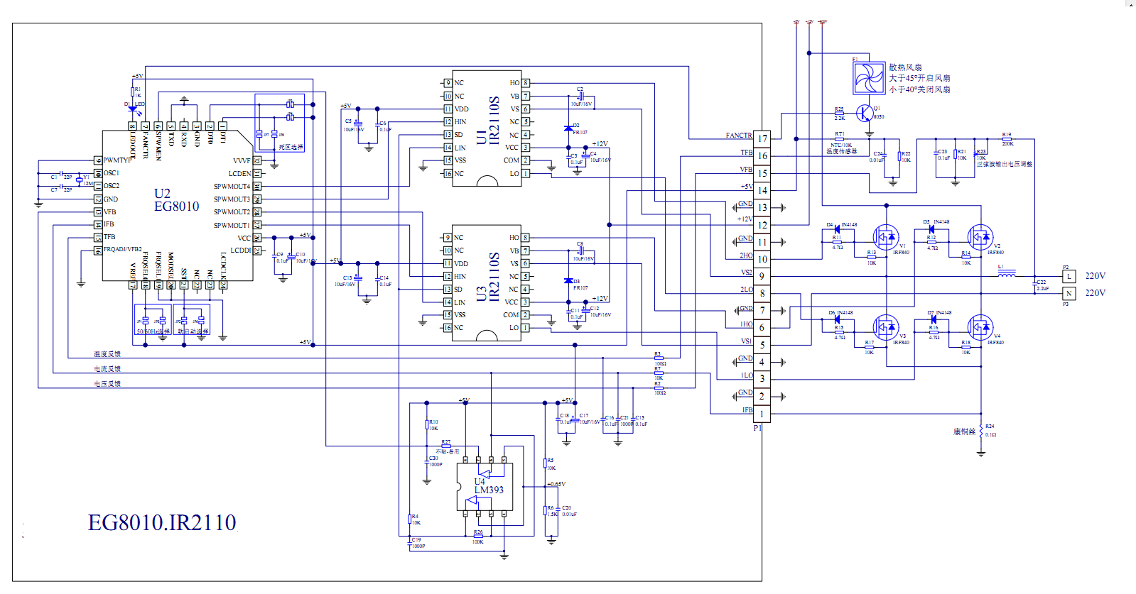
tahmid ,,can u plzz give me complete schematics with component list of smps based inverter around 500watt ,,, it will be very important to me ,
 

tahmid ,plzz tell me how to select high frequency transformer for 800watt inverter(specifications and name )
 

Since you are new to this, I suggest you attempt to construct an inverter of smaller capacity. Try with 200W. Start with a frequency of 50kHz. You can easily use ETD39 for 200W and more. You can wind the transformer yourself using multiple strands of thin wire or Litz wire.
 
Thanx jestin .....
The data in the that link u have attached is in chinese language ...can u plzz send me it in english .....

- - - Updated - - -

Tahmid ...I have a computer smps 200w
Plz tell me that can I use the transformer of that smps for making inverter??? If yes den what will be output power ???the computer smps transformer has 5input n 2 output pins and one wire is coming from upward side plz tell me how to select inlut and output pins ??also tell me how to calculate the values of inductor n capacitor which I will be using in output to make it sine wave (filter)..
 

You need to rewind the transformer if you want to use it. The 12V winding is probably rated at 10A or lower. So, that would give you a maximum output of 120VA. But the output will be very low. You can use the 5V winding but the output peak could become too high. It's just better you rewind the transformer as required.
 
Readymade board of above schematic is also available.

6317099900_1354710945.jpg
 

tahmid ,please tell me how to select the gauge of wire used for winding the etd 39 cores,,for input as well as output side,,???

- - - Updated - - -

plzz give me complete tutorial of winding the ferrite core transformer i.e. wire specifications, operating frequency,output and input power,,,??
 

You need to use wires so that they can handle the total current without heating and also without suffering significantly from skin effect.
 
Links to charts of wire gauges showing thickness, feet per ohm, safe amp-carrying capacity:

http://amasci.com/tesla/wire1.html


http://www.powerstream.com/Wire_Size.htm

Here's a link to another wire gauge table. Its ampacity values are much different than the other tables.

**broken link removed**

Possible reason for the disparity: One source may base ampacity on a higher temperature which makes the wire get too hot to hold, while the other source may use a lower temperature where copper's electrical characteristics start to change even though it is only warm.
 
In some ferrite transformer there are 5 pins in input ,,,what does it mean???i mean if i hve to convert 12 volt to 311 volts ,then i will use centred tape transformer ,,that has only 3 input pins,,,so in a ferrite transformer of 5 input pins ,,,what is the role of extra 2 input pins,,,,,
and also plzz tell me if i have to convert 12 volt to 311 volt,,should i use centred tape ferrite core transformer or simple 2 pins input transformer(power is around 500 watt)???

- - - Updated - - -

what is the difference between half bridge and full bridge ??
 

The extra two pin is for feed back,and you will need to use center tap for the transformer , difference between half bridge and full bridge is that the half bridge uses center taped and the full bridge doesn't use center taped it uses four transistors that switched the transformer ,you can google search for more info..
 

In some ferrite transformer there are 5 pins in input ,,,what does it mean???i mean if i hve to convert 12 volt to 311 volts ,then i will use centred tape transformer ,,that has only 3 input pins,,,so in a ferrite transformer of 5 input pins ,,,what is the role of extra 2 input pins,,,,,
and also plzz tell me if i have to convert 12 volt to 311 volt,,should i use centred tape ferrite core transformer or simple 2 pins input transformer(power is around 500 watt)???

It depends on the transformer and the circuit. The 2 extra pins could be for feedback or for an auxiliary supply. In my inverter designs, I use an extra winding on the transformer (2 pins) for an auxiliary power supply to use for powering the circuitry and driver section on the secondary side to keep it isolated from the primary side.

If you use full-bridge, you won't need a center tap. If you use push-pull you will need a center tap.
If you use full-bridge, you'll need double the number of MOSFETs than you will for push-pull. You will also need a more complex driver circuitry to drive the 4 MOSFETs, 2 of which will be configured as high-side switches.

For 500W, push-pull can be used. You don't need to use full-bridge. But you can use it if you want.

Hope this helps.
Tahmid.
 
thanx tahmid,,,,,,plzz tell me the gauge of wire (input and output) used to make 500 watt inverter also tell me the ferrite core no..?? i have to buy the wires tomorrow,,so also tell me aprox length of wire used(input and output)???
 

You should be able to use ETD49 or ETD54 quite easily if you use a frequency greater than 30kHz. As for length of wire, I'm not sure. You can probably calculate it, but you could also just wind the wire or a piece of string across with the required number of turns and then measure/compare the required length of wire.

Hope this helps.
Tahmid.
 

thanx again tahmid,,i hve still one cofusion ,,suppose my primary voltage is 12v and my secondary voltage is 311 volts and power is around 500VA, then what will be the no. of input and output turns respectively..i mean there are many posibilities of choosing the input and output turns so that the turn ratio is equal to 311/12...so can i select the correct one fot ETD49 core..???and also tell me that Is the method of winding the CENTRE TAPE ferrite core transformer is same as that of normal iron core transformer??
 

I think you should search for similar tread in this forum someone upload some reference sheet concerning transformer calculations.
 

So, your voltage conversion requirement is 12VDC to 311VDC.

Let's take minimum battery voltage where load must still be driven as 10.5V. So, you'd still need 311VDC at that input voltage. Let's take maximum duty cycle as 95%. So, at 10.5VDC input, duty cycle will be maximum. Average voltage to transformer will be 10.5V * 0.95 = 9.975V. Thus voltage ratio is (311V/9.975V) = 31.18. Let's leave some headroom to allow for losses and voltage drops and some headroom for feedback. So, let's take a voltage ratio of (340V/9.975V) = 34.1.

Formula for calculating primary turns is:

Npri = (Vinnom * 10^8) / (4 * f * Bmax * Ac)

Ac (or sometimes called Ae) is in cm^2, Bmax is in Gauss, f is in Hertz, Vinnom is in Volts.

Get Ac and Bmax from transformer datasheet.

For ETD49, from the datasheet I have, I get Ac = 2.36
I'll take Bmax to be 1300. Most cores will be okay with that.
Vinnom = 12V

Let's take a switching frequency of 50kHz.
f = 50000

So, I get Npri = 2 turns (rounded off)
Check Bmax.
Bmax (with Npri = 2) comes out to 1271. If that's too high, increase Npri. But 1271G should be okay for most cores.

Nsec = (Turns Ratio) * Npri
Turns Ratio = Voltage Ratio = 34.1
With Npri = 2, Nsec = 68 (rounded off).

Now, wind with a sufficient number of thin wires in parallel to minimize wire resistance and skin effect. Or use Litz wire.

There you have it.

Hope this helps.
Tahmid.
 
Thanx a lot tahmid....it was very helpful for me
U have told that primary winding will consist of 2turns secondary winding has 68 turns .I want to ask that if
I take 4 turns in input side and 136 in secondary , the turn ratio is still same but the input and output impedence of the
Transformer is now changed and we all know that maximum power will transfer to the output circuit if the output impedence
Of Transformer is equal to input impedence of circuit (mosfet) so my question is how to select the appropriate no. Of turns so that maximum
Power can be transfered ???
 

Status
Not open for further replies.

Part and Inventory Search

Welcome to EDABoard.com

Sponsor

Back
Top