Continue to Site

Welcome to EDAboard.com

Welcome to our site! EDAboard.com is an international Electronics Discussion Forum focused on EDA software, circuits, schematics, books, theory, papers, asic, pld, 8051, DSP, Network, RF, Analog Design, PCB, Service Manuals... and a whole lot more! To participate you need to register. Registration is free. Click here to register now.

pulse transformer circuit diagram needed

Status
Not open for further replies.

puffadder

Newbie level 3
Newbie level 3
Joined
Jun 3, 2012
Messages
4
Helped
0
Reputation
0
Reaction score
0
Trophy points
1,281
Activity points
1,322
my project is to make inverter. here i have to use mosfet driver to isolate mosfet at full bridge connection. pwm signal is given to the gate. i need full circuit diagram of the pulse transformer.plz let me know about the transformer in details.
 

Dear puffadder
Hi
Why pulse transformer ? why not a simple driver ? but if you want use transformer , there isn't any specific problem ! you'll just need a totem pole before your transformer ( with a series capacitor ) and an RCD network in primary !
BTW : how did you create your PWM signal ? with an IC ? or perhaps a micro controller ?
Best Wishes
Goldsmith
 

thanks for the reply. i have used atmega8 to generate sine pwm(50 hz sine wave with 800 hz triangular wave). plz, give me the pulse transformer circuit diagram(with totem pole).my teacher prefers pulse transformer than other.

- - - Updated - - -

thanks for the reply. i have used atmega8 to generate sine pwm(50 hz sine wave with 800 hz triangular wave). plz, give me the pulse transformer circuit diagram(with totem pole).my teacher prefers pulse transformer than other.
 

Dear puffadder
Rather than using Pulsed Transformers, you can use H-bridge driver ICs e.g L6384 can be used in pair for the four switches.
 

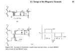
Humm ! see below , please :
Transformer driver.JPG
Best Wishes
Goldsmith
 
  • Like
Reactions: dselec

    dselec

    Points: 2
    Helpful Answer Positive Rating
dear Goldsmith,
why BJT at transformer primary side? and where the pwm signal will be given?and is the BJT ground different from transformer primary side ground? i give pwm signal directly to the transformer and at secondery side i found just spike with small amplitude instead of copmplete pulse.
 

Hi again
That bjt arrangement called AC totem pole , and prepared to produce enough current to drive transformer . for top circuit , at that page you should use a not gate , and then give your PWM into that , and thus you'll have PWM for base of top bjt , and PWM' for down side bjt .
and the circuit in down of that page , ise some thing like an H bridge , it can give you more currents .it is enough to drive more mosfets .
Best Wishes
Goldsmith
 

Hi Goldsmith,

Any idea on how to design above pulse transformer with parameters like no. of turns, magnetic core selection, wire sizes?
Is there any ready made miniature SMD pulse transformer available? I found most pulse transformer too bulky and big.

Thanks in advance with regards,
micropar
 

Hi Micropar
you can easily calculate your pulse transformer . but at first you should select your mosfets and then calculate required IG ( Iciss ) and then consider it in your calculations . most of the times pulse transformers are 1:1 but it is possible to design it with other considerations too . by the way are you familiar with core selection process and transformer calculations ? if no i can give you a simple way .
ABout lower size pulse transformers , some years ago i saw pretty low one , i think its size was axial 0.8 !!!! but it's wire was pretty elegant .
Best Wishes
Goldsmith
 

I'd recommend against using a gate drive transformer for an inverter. For it to work properly at all, you need DC restoration circuits on the secondary, like what goldsmith posted above. But such circuits can cause spectacular failures if they're not handled properly. In particular, any sudden change in duty cycle will cause the Vgs waveform to change it's DC bias for a while, and this can easily cause cross conduction. You should only consider using such a method if you have sophisticated control schemes which prevent this from ever happening during normal operation and fault conditions, including in the case of an unexpected loss of power to the controller.
 

Hi Goldsmith and Mtweig,

Thank you all for comments. On more thinking, I remember 2 or 3 old application notes from Unitrode that discusses about pulse Xformers as well as its series capacitor selection in great length. I need to search in my backup as well as TI site, since it had taken over the Unitrode. I will be glad to post here the same if I come across.

Regards,
micropar


I've worked with a leading power module company and to
them a "pulse transformer" may be nothing but a pair of
coupled PCB traces, or a wound transformer, depending.
They represent it as such, but there's not necessarily any
"circuitry" behind it.
 

Hi again
I though perhaps it will be a good point to mention for each people that see this thread :
Transformers are good choices when you don't want carry SPWM with them . ( they are ok for PWM , however not most of the times ! ) but for SPWM , it is impossible to use transformer .
Best Wishes for all
Goldsmith
 

This looks like a better description of a very low cost pulse transformer design for high capacitive loads.
The details in the transformer are good. 1 or two turns, 10nS response cheap, >5KV isolation. Almost like a TV splitter core.

https://www.how2power.com/newsletters/1203/articles/H2PToday1203_design_FerenczConsulting.pdf
This is a neat circuit, but it carries the same limitations as other gate drive transformer schemes, mainly that it won't function properly with very low or high duty cycles. Also it still requires a DC supply on the secondary side for each gate.

Gate drive transformers are fine for applications where the duty never has to go much beyond 50%, and it doesn't have to cover a large range, or change very quickly. Under any other circumstances, there will be risk of the DC bias changing enough to cause failure.
 

I might add that the implementation I am talking about, was
a resonant converter that does PFM, not PWM. Much easier
to tune a transformer type gate circuit (which had some
interesting stuff between xfmr and gate to make it work)
when you have a limit range of pulse width variation.
 

This common gate transformer coupled driver claims to support wide duty cycle ranges
Now this is a scary circuit... after the transformer saturates, the driver is a very high impedance and it simply relies on the gate capacitance maintaining its charge. Any significant of interference or coupling to the gate during that time and boom. I wonder if anyone ever tried using this scheme in an actual product?
 

The latter schematic comes from IRF and is just detailed enough to show the theory of operation. It appears to be a bang bang switch bipolar Set Reset pulses to close the switch. At this time the impedance of the core does not matter as the saturation current has charged up the gate capacitor to provide the necessary current to activate the switch, after which the gate can relax. Capacitor discharge is an effective means to force MOSFET gates to switch quickly given the intrinsic gate to source capacitance.
 

after which the gate can relax.
I think most power engineers won't accept this condition. When driving a FET, the driver should hold its state with a low impedance all the time. Otherwise any transient voltages on the drain can couple to the gate via Crss, causing undesired turn on and turn off. And such transient effects should be expected in practically all scenarios (line surge, load dump, etc).
 

Status
Not open for further replies.

Similar threads

Part and Inventory Search

Welcome to EDABoard.com

Sponsor

Back
Top