Vermes
Advanced Member level 4
Assumptions:
- short circuit protection
- resistance to mistakes such as reversed connection of the amplifier
- 250W continuous power
- additional output voltage +/- 9...12V of low current efficiency (to supply the preamplifier, fans, etc.)
Schematic:
Board (150x100mm) in a graphical format:
Assembly diagram in a graphical format:
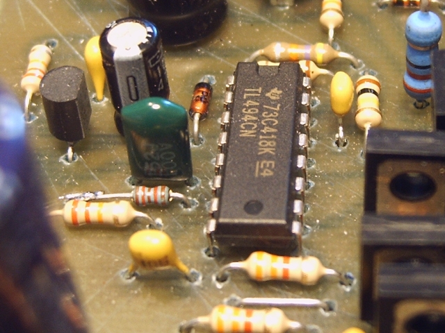
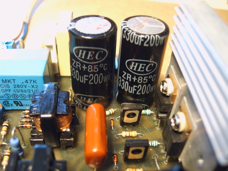
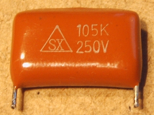
Converter consists of few basic modules present in most SMPS, such as ATX power supply. A fuse, thermistor and mains filter consisting of C21, R21 and L5 were placed on 230Vac power. Also rectifier bridge D26-D29, input capacitors of the converter (C18 and C19) and power transistors Q8 and Q9 switching the voltage on the transformer. Power transistors are controlled via additional transformer T2 by one of the most popular PWM controllers – TL494 (KA7500). Current transformer T3 to measure the output power is connected in series to the primary winding. Transformer T1 has two separate secondary windings. One of them generates voltage 2x35V, other 2x12V. Fast diodes D14-D17 and D22-D25 are placed on each of the windings. They make two Graetz bridges. Chokes and output filter capacitors are placed behind the bridges.
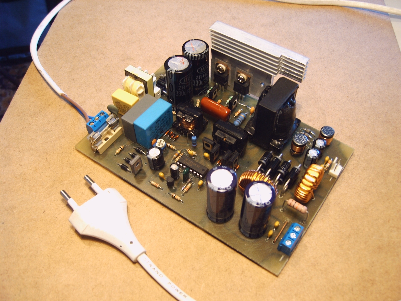
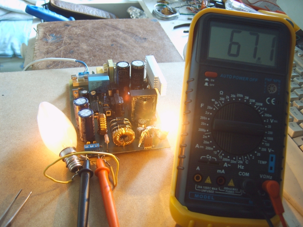
Pictures of model system:
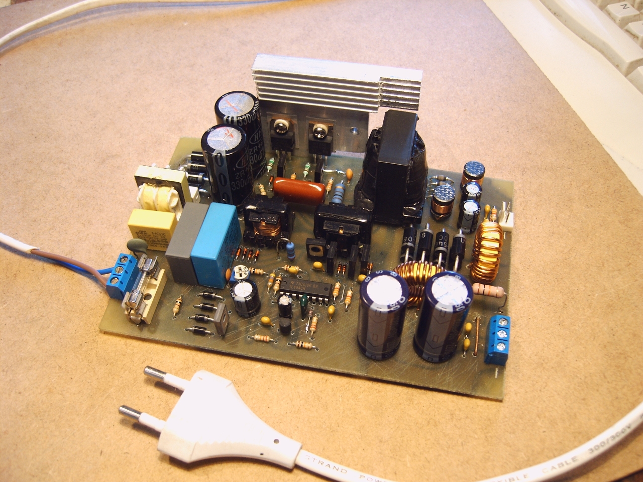

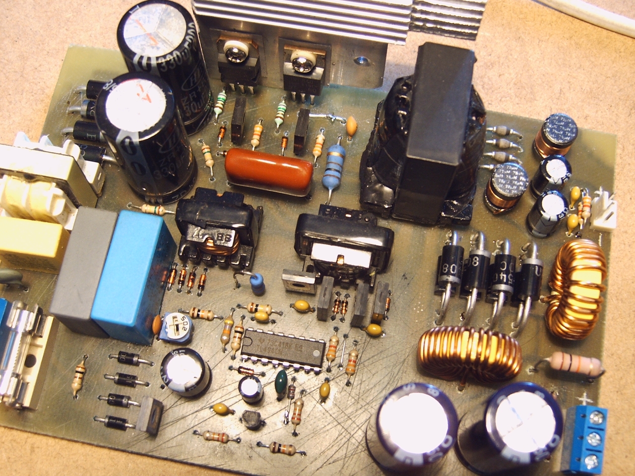


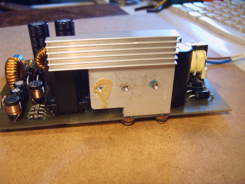
The system was made to supply two amplifiers TDA7294. Transformer was wound on a core from ATX power supply, of very similar dimensions to ETD29. Number of turns are given on the schematic. Output voltages are respectively: +/-34V and +/-10,5V. Tests started with placing capacitors 470uF on line +/-34V and output chokes 6,8uH/14A:
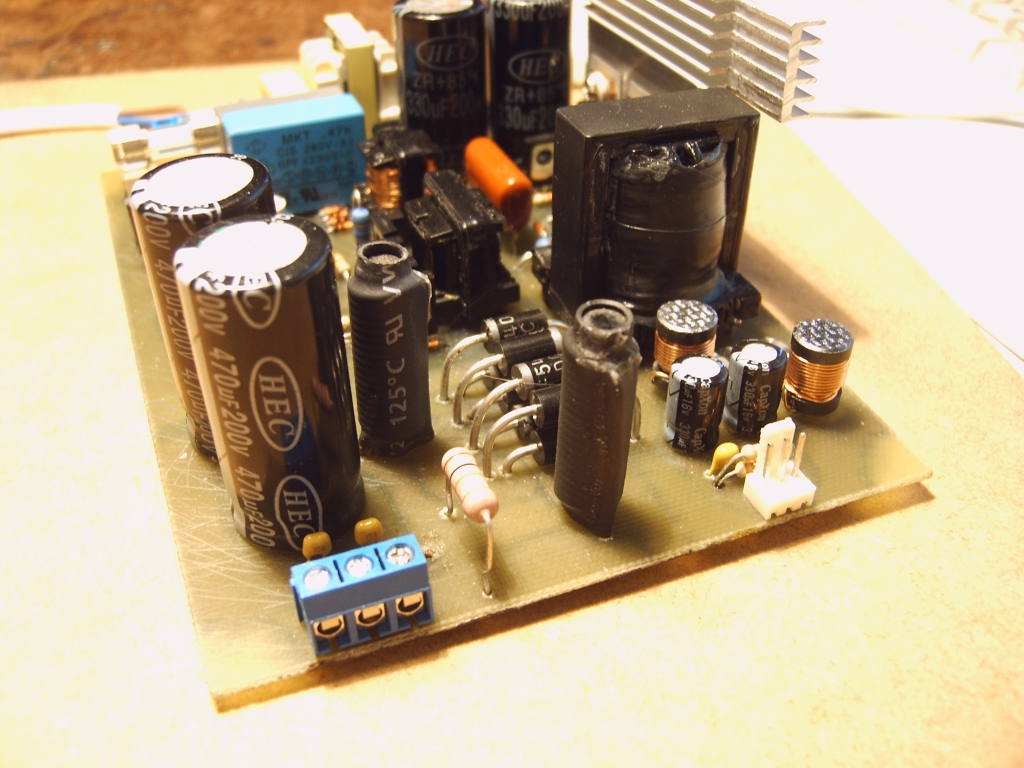
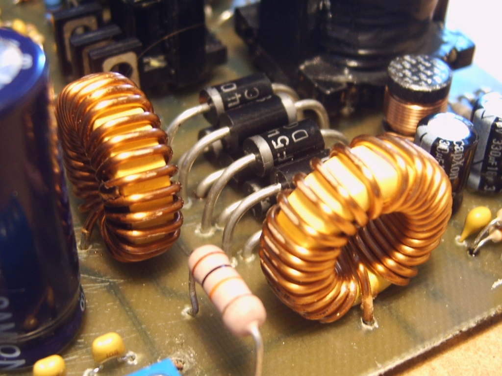
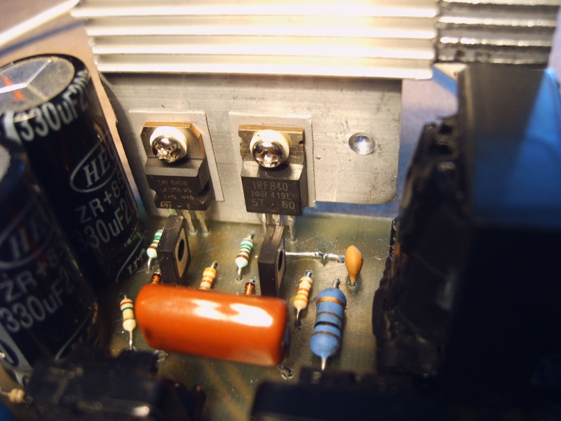
After loading +/-34V line with 14ohm resistive load, voltage drops to +/-31V. It is quite a good result as for such a small ferrite core. After 5 minutes, diodes D22-D25, main transformer and mosfets heated up to about 50 degrees Celsius. After connecting and setting two TDA7294 channels, voltage dropped to +/-30V. Elements of the converter heated up like with resistive load. The final system was equipped with output capacitors 2200uF and chokes 22uH/14A. Voltage drops are quite larger than at 6,8uH (to +/-30V), but heating mosfets decreased (in tests after few minutes at about 250W mosfets heated up to 40 degrees Celsius).
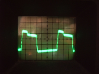
Output voltage at both outputs loaded with lamps, power 20W:
And other pictures:
Link to original thread (useful attachment) – Zasilacz impulsowy do zastosowań audio 250W - projekt