Continue to Site

Welcome to EDAboard.com

Welcome to our site! EDAboard.com is an international Electronics Discussion Forum focused on EDA software, circuits, schematics, books, theory, papers, asic, pld, 8051, DSP, Network, RF, Analog Design, PCB, Service Manuals... and a whole lot more! To participate you need to register. Registration is free. Click here to register now.

[SOLVED] Problems with 7912 regulator

Status
Not open for further replies.
I've checked the input entrance of the 7912 and its only -6.3Vdc, also I checked the transformer voltage and is still 14-0-14. ... Maybe I've damaged the 7912 as you said alexan_e . Sadly I don't have another regulator, I'll try to get one as soon as I can!
 

good how recheck your connection for the 7912 what is the voltage at pin 1 2 3 regarding grd=centertap
7912 neg reg .PNG
 

If the input is so low then there must be something else wrong.
Disconnect the 7912 , what is the voltage there now (referenced to the ground which is the center tap)

Are your negative side caps Ok, maybe they were exposed to a reverse voltage and they have been damaged.
 

I've checked the input in the 7912 and is just -6.3 Vdc. Maybe as you said alexan_e I damaged the regulator. Is that the only possibility? I'm gonna get a couple of 7912 right away :)

---------- Post added at 11:47 ---------- Previous post was at 11:32 ----------

I've just checked only the 7912 as you said alexan_e, and it is still with the problem of -4.5 Vdc in the output. Does that mean that the regulator is damaged?
 

That is not what I said.
What I said was to disconnect the 7912 and check the voltage you get at D2 output (where the 7912 input was connected)
 

oh, I misunderstood ... sorry about that... I took off the 7912 and checked the voltage in the diode's anode that was connected to it and is -18Vdc aproximately. Then I put back the regulator and measured the voltage in the input of the 7912 regulator and it is -6.3 Vdc.

---------- Post added at 12:07 ---------- Previous post was at 12:04 ----------

Thanks dselec, I checked that connection, at least its working in the positive side, but now I have that little problem of low voltage in 7912 output (- 4.6Vdc aprox)

1=grn
2=in
3=out did u see my drawing ?
there is a internal zener in the 79.. and i think its about 4.7v so the 79.. is bad ,but before remove the 79.. and attach 220-510 ohm resistor butween pin 2 and grd and post result.
 
Last edited:

If the cause of the voltage drop is the 7912 pulling current then it should get hot too, does it?
When you have the 7912 connected and you measure -4.6v DC, what is the AC voltage at the same point?
Also what is the AC voltage from the center tap to the transformer end that feeds D2?

---------- Post added at 18:15 ---------- Previous post was at 18:13 ----------

1=grn
2=in
3=out did u see my drawing ?

I have asked him about the pinout in post #5 and he said it was OK.
 

Thanks dselec, I saw your drawing, I took that in consideration for regulator conections. It doesn't really get hot alexan_e, it gives me low voltage only. I measured the center tap - end transformer wire and it's 13.5 VAC, which I think is OK. Also i measured 0VAC in the output (where is -4.6Vdc), is it important to measure the AC voltage in this point?

---------- Post added at 12:27 ---------- Previous post was at 12:21 ----------

also I'm testing with a 1K resistor and a LED in each output. I've noticed that there's a voltage dropout from each one when I do that, from the 7812 which normally gives me +12V, now it's 9V, and from the 7912 just drops to -4.5Vdc from the -4.6Vdc. Is there any way to stabilize a little more the outputs?
 

Well now that u have a good +12 volt pwr supply u can use it to cheek your 79xx reg like that in this drawing ....
opps coffee break got to go can u help him here alex.?
 

OK so you have 13.5v AC which is rectified and gives -6.3 DC to the input of 7912 and then -4.6 DC and 0v AC to the output of 7912?
What is the AC voltage in the input of the 7912?

The AC at the transformer is fine so I don't see a transformer problem, the AC in the input of the 7912 can show if there is a problem with the capacitor.
It's strange to have 13.5v AC in one side of the diode and -6.3 DC in the other without any AC.
 

Thanks dselec, I saw your drawing, I took that in consideration for regulator conections. It doesn't really get hot alexan_e, it gives me low voltage only. I measured the center tap - end transformer wire and it's 13.5 VAC, which I think is OK. Also i measured 0VAC in the output (where is -4.6Vdc), is it important to measure the AC voltage in this point?

This is weird for a simple regulator thread to get 30 post long.

you must realize

1.that you cannot connect both positive and negative regulator IC in same pin out manner.
2. It is a very simple device with least protections more0ver negative regulator blows off quicker than positive(my own experience)
3.Do confirm that you did not buy counterfeit Ic's or dealer did not cheat you with damaged ones.
4. There is no talking of AC when you are dealing with voltage regulator IC. all ac should be left behind the rectifier Diode at transformer end.
5.replace the IC and check again after going through entire thread again ,
6.make very sure about pin layout and the metal TAB on top of the IC is Live, that is it shouldn't be touched with ground

happy building
cheers
 

I tried what you said dselec, I took off the 7912 and then I put a 330 ohm resistor between the spots where were pins 2 and 3 of the regulator. It gives me -18Vdc aproximately. It seems that the transformer is working properly, at least I think it does... About the dropout that I mencioned, is it any way I can get a stable voltage? or is it wrong to test it with a 1K resistor and a led in the output.
 

Yes alexan_e, I also measured the AC voltage in the output of the 7812 and it is 19 Vac, in the input there's 24.5 Vac... now I'm a little confused because I expected a lower value ...anyway ...I imagine there should be a similar value between pin 3 and pin 1 in the 7912 but it gives me 0Vac. In the input of the 7912 there's 13.5Vac.
 

1=grn
2=in
3=out did u see my drawing ?

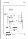
why 2-3 i said minus input and grd7912 neg reg.PNG
 

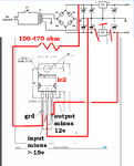
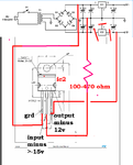
dselec, in your diagram you're connecting pin 1 from the 7812 through a resistor to the pin 1 of ic2, and also pin 2 from 7812 (GND) to ic2's pin 2, is that right? ... I don't understand quite well why are you doing that, if you could explain it I would really apreciate it.
 

OK
I will answer your question by asking u a question .. i will guarantee u will learn electronics this way better.
i changed the diagram a bit so u will understand better
7912 neg reg.PNG
first disregard ic1.....and disconnect ic2..and add a 470ohmm resistor parallel to c4 and post your reading u should get 18 volts.
now next actually I see pin 1 as negative voltage with ref to grd ...right ? if u check with fluke blk lead to pin1... and red to pin 2... u will read -18volt.. right ?
check-it out.
so now my grd is pin 1 and pin2 is minus.. -18 v ..right ? so now u got - volt from pin 2 thru current limuting resistor to neg input of ic2 and pin 1=grd in grd of ic2...right ? so all u have to do is check voltage between pin1=grd of ic2 and pin3 of ic2 and get a reading that u do and tell me what u get.
remember u can take 2 readings with fluke black lead to grd=pin 1 ic2....to( red lead of fluke)pin2 ic2 getting -18v and to pin3 of ic2 getting -12v...try it out.
remember ic2 really does not know whats going on with all the other components all he cares is he is getting -18 to pin 2 with ref to pin1=grd. your answer will tell if ic2 is bad.

good luck
 
Last edited:

dselec, I've tried your way, first i took off ic2 and put a 330 ohm, 1/2W resistor between pin 1 and pin 2 of ic2(already taken off of course), but it gives me -10Vdc aprox (black lead in pin 1 and red one in pin 2), and the resistor gets really hot pretty soon, and there is 0Vdc in the output of ic1. I understood what you meant with your explanation, although I think there's something else going on....and I don't know what it is... also I managed to get another 7912 and it's the same thing, so I guess is not a 7912 problem.

---------- Post added at 17:12 ---------- Previous post was at 17:05 ----------

I've measured the input voltage without the 7912 (in the anode side of the rectifier diode) and its -18Vdc, but as soon as I put the regulator on, the voltage changes to -6.3Vdc, I've tried two different 7912 and it's the same behaviour, I'm not pretty sure what to do next.
 

Status
Not open for further replies.

Similar threads

Part and Inventory Search

Welcome to EDABoard.com

Sponsor

Back
Top