Continue to Site

Welcome to EDAboard.com

Welcome to our site! EDAboard.com is an international Electronics Discussion Forum focused on EDA software, circuits, schematics, books, theory, papers, asic, pld, 8051, DSP, Network, RF, Analog Design, PCB, Service Manuals... and a whole lot more! To participate you need to register. Registration is free. Click here to register now.

Problems in Relay control circuit using MCU

Status
Not open for further replies.

kelip

Newbie level 5
Joined
Apr 14, 2010
Messages
8
Helped
0
Reputation
0
Reaction score
0
Trophy points
1,281
Location
Malaysia
Activity points
1,355
Hi, i have problem in my project. I'm doing automatic system that turn ON pump when alarm time that has been set reached. I'm using external RTC (DS1302) for real time clock.

When i test the system without connecting the pump to relay, it works fine. But, when i connect the the pump into the relay, problems occurred. The problem is that after the pump turn ON in 1minute, the system not continued to count the time which means its freeze.

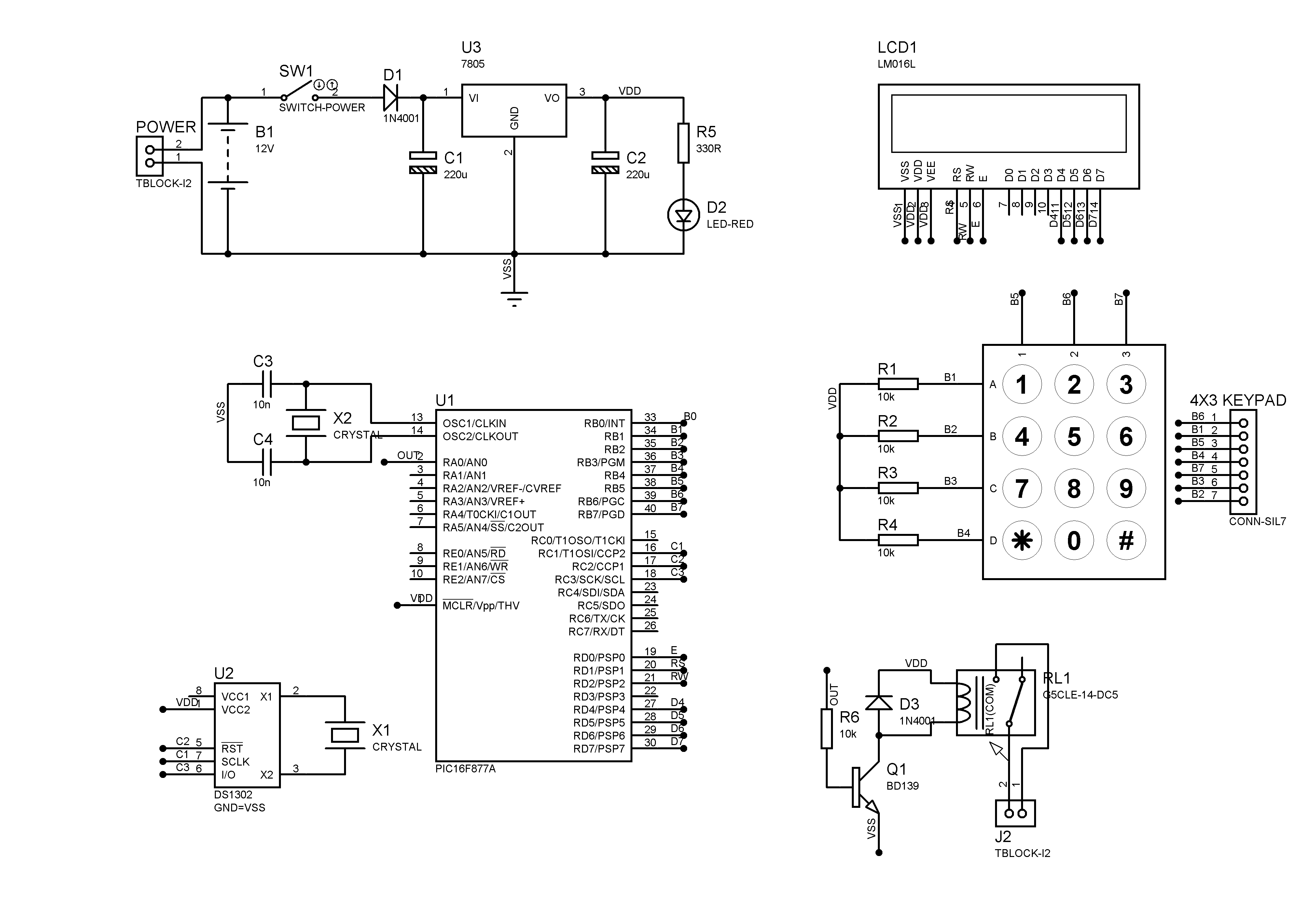
Here the schematics for this project:


Help me~~~~
 

system is not working when the relay is ON.. is it correct??
just check that whether the supply voltage is dropping when the relay is ON..
 

I'm using 5v coil relay to turn ON/OFF water pump with 240V. I share the 5v coil with MCU 5v. By sharing them, is it has effect to the system?
 

If you use any interrupts check that there isn't anything that locks the mcu (stuck in the interrupt).
You can also add a led to a pin and have it blinking while the timer is counting and reaches a value,
it would indicate if the timer works or not.

Alex
 

Add a optocoupler is recommedded.

---------- Post added at 09:28 ---------- Previous post was at 09:27 ----------

Another respect is that your power supply is not supply the enough current to the relay.
 

Another respect is that your power supply is not supply the enough current to the relay.

The base resistor is 10k which would give a base current of about 0.5ma he will get about 20-25mA in the output at about 2.5-3v,
but he says "after the pump turn ON in 1minute" so I guess the relay turns on and the problem is created after that.

The base resistor should be lower anyway , about 1-2k

Alex
 

check that the supply voltage is staying at 5V after the relay ON?
if it is not your power supply is not delivering enough current to your system...
 

Thanks for all reply.

I check the supply after relay ON and the result shows the voltage stay at 5v and not drop.
Also, I have change following:

1. Change 10K resistor to 1K ohm
2. Add another voltage regulator (7805) circuit for separate the voltage supply for MCU and relay. Which means both circuit get enough current. Right?

But the result also same. The time (RTC) are not counting after the relay ON (when alarm).

Alex. regarding for the interrupts, i think its possible. I'm using CSS Compiler. Here is the programs:

#include <16F877a.h> //include pic16f877a file header
#include <stdio.h> //include standard input/output header file
#fuses hs,noprotect,nowdt,nolvp,NOBROWNOUT,PUT //internal fuses for this type of pic
#use delay(clock=20000000) //set clock frequency/oscillator (20MHz)

#define use_portb_kbd TRUE //define port b for keypad

#include <ds1302.c> //include source file for RTC ic
#include <lcd.c> //include source file for lcd 16x2
#include <kbd.c> //include source file for phone keypad

#byte porta=5 //define address for each port
#byte portb=6
#byte portc=7
#byte portd=8

int hour,n,min,sec; //define type of general variables
int status=0; //define and initialize value for status
//of alarm counter

int get_number() { //function for get two digit no
int first,second;

do { //for 1st digit
first=kbd_getc();
} while ((first<'0') || (first>'9'));
lcd_putc(first);
first-='0';

do { //for 2nd digit
second=kbd_getc();
} while ((second<'0') || (second>'9'));
lcd_putc(second);
second-='0';
delay_ms(1000);

return((first*10)+second); //return the value when this function was called
}

void set_clock(){ //function for set clock
int day,mth,year,hour,min;

lcd_putc("\fYear 20: ");
year=get_number(); //call function get_number and store to variable year
lcd_putc("\fMonth: ");
mth=get_number(); //call function get_number and store to variable month
lcd_putc("\fDay: ");
day=get_number(); //call function get_number and store to variable day
lcd_putc("\fHour: ");
hour=get_number(); //call function get_number and store to variable hour
lcd_putc("\fMin: ");
min=get_number(); //call function get_number and store to variable minutes

rtc_set_datetime(day,mth,year,0,hour,min); //set RTC by using all variable earlier
}

void set_alarm(){ //function set alarm
int i,set1,set2; //set1 for hour, set2 for minutes

lcd_putc("\fAlarms/day \n(max=9): ");

do { //get no of alarms ( maximum 9)
n=kbd_getc();
} while ((n<'0') || (n>'9'));
lcd_putc(n);
n-='0';
delay_ms(1000);
write_eeprom(0,n); //store no of alarms

for(i=2;i<=n+1;i++)
{
printf(lcd_putc,"\fSet Alarm %u \nHour: ",i-1);
set1=get_number();
write_eeprom(i,set1); //store set1 in memory address i
printf(lcd_putc,"\fSet Alarm %u \nMinutes: ",i-1);
set2=get_number();
write_eeprom(i+9,set2); //store set2 in memory address i+9
}
}

void alarm() //function alarms for check the alarm status
{
rtc_get_time( hour, min, sec ); //read real time clock data
//write_eeprom(1,status); //store curent count of alarm in address 1

if (status<=read_eeprom(0)) //check if current status less than no of alarms set
{
if (read_eeprom(status+2)==hour&&read_eeprom(status+11)==min&&sec==0) //compare the clock and current alarm
{
output_high(pin_a0); //turn ON relay
lcd_putc('\f'); //clear LCD
lcd_putc("IT'S TIME!!!!");
delay_ms(60000); //adjust delay for relay ON time
status=status+1;
write_eeprom(1,status); //store curent count of alarm
}
else
{
output_low(pin_a0); //turn OFF relay
status=status; //stay on current status
}
}
else
{
status=0; //if current status greater than no of alarms, reset status
}
}

void main() {
char cmd;
int hour,min,sec,curent,hour_alarms,min_alarms;

set_tris_a(0x00); //set port A as output

rtc_init();
lcd_init();
kbd_init();

write_eeprom(1,status); //store curent count of alarm in address 1

lcd_putc("\f1:Set Time&Alarm\n2:Set Alarm");

do {
cmd=kbd_getc(); //choose mode
} while ((cmd!='1')&&(cmd!='2'));

if(cmd=='1')
set_clock(); //call function to set clock
set_alarm(); //call function to set alarms

while (true) {
lcd_putc('\f');
rtc_get_time( hour, min, sec ); //read real time clock
alarm(); //call function alarms to check status alarm
curent=read_eeprom(1); //read status no of alarm
hour_alarms=read_eeprom(curent+2); //read hour of alarm
min_alarms=read_eeprom(curent+11); //read minutes of alarm
printf(lcd_putc,"TIME=%d:%d:%d \nAlarm at %u:%u",hour,min,sec,hour_alarms,min_alarms);
delay_ms(250);
}
}
 

Attachments

  • RTC_ALARMS.rar
    1.7 KB · Views: 91

I check the supply after relay ON and the result shows the voltage stay at 5v and not drop.

The positive supply of the relay is connected to the Vcc, it will always have 5v...
Your transistor provides the gnd to the relay, it can leave the lower coil side floating or it sinks current (provides gnd),
you have to measure the voltage in that point to see what voltage do you have (not 0 because of the Vce),
check that it is enough to turn your relay on, you probably had a problem with that with the 10k resistor but with 1K i think you are ok.

I haven't used CSS but I'll take a look.

Alex
 

you can probably try this exercise:

Remove the Pump load out of your existing relay and connect it to another relay. The Coil (5V or 12V) of that another relay, let it go through your existing relay.
This could let you identify whether the microcontroller hangs due to interference when the load is switched. This is not a final solution, its is just to figure out whether is that the problem.
 

connect LED instead of relay and check whether the circuit works properly. if it works well there is a problem in the relay part only...
let me know the result..
 

Hi, i have problem in my project. I'm doing automatic system that turn ON pump when alarm time that has been set reached. I'm using external RTC (DS1302) for real time clock.

When i test the system without connecting the pump to relay, it works fine. But, when i connect the the pump into the relay, problems occurred. The problem is that after the pump turn ON in 1minute, the system not continued to count the time which means its freeze.


Help me~~~~

Never ever saw BD139 to drive a 5V relay. Replace with BC547.
Thankyou
 

looks like the problem is the pump..
can you give some specs of the pump
pump voltage, current, DC or AC.
if the pump is DC and ground is common try to separate the ground connection of the pump and your circuit and also connect a free wheel diode across the pump as well (only if the pump is DC)
for the controller side enable the watchdog timer. and try blinking some led after a fixed interval so that you can see whether your controller is hanging or the RTC...
 

looks like the problem is the pump..
if the pump is DC and ground is common try to separate the ground connection of the pump and your circuit and also connect a free wheel diode across the pump as well (only if the pump is DC)

I think its mentioned in Post #3 that the pump is 240V , and i dont think it can be DC.
 

sorry my mistake i missed out that one..
OK then try some By pass capacitors in the power supply section and on controller's MCLR pin,also near to the supply pins of both controller and RTC. there must be some spikes generated whenever the PUMP is started..
also increase the value of the filter capacitors in the power supply this will stabilize the voltage when the voltage gets down during pump startup..
 

I think its a good idea to change BD139 to BC547, add by pass capacitor to MCLR pin and add LED to relay circuit. I'll try it. I'm using AC pump (240V). I will update the status soon.
 

Status
Not open for further replies.

Part and Inventory Search

Welcome to EDABoard.com

Sponsor

Back
Top