Continue to Site

Welcome to EDAboard.com

Welcome to our site! EDAboard.com is an international Electronics Discussion Forum focused on EDA software, circuits, schematics, books, theory, papers, asic, pld, 8051, DSP, Network, RF, Analog Design, PCB, Service Manuals... and a whole lot more! To participate you need to register. Registration is free. Click here to register now.

problems facing in closed loop control

Status
Not open for further replies.
The "free lunch" saying is quite often quoted at Edaboard when talking about design trade-offs.

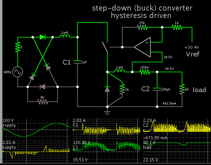
It this case, it means that the tricky topology most likely involves higher EMI than industry standard PFC designs. There's a reason why commercial PFC power supplies use a different topology.

So what is your suggestion now to improve the EMI??as it is too late to change the topology..What measures should i take now to decrease the EMI if not eliminate entirely????
 

I expect that the already provided filters give acceptable EMI in a regular PCB. The first series inductors could be replaced by a common mode chokes, smaller X (or Y, if PE is available) capacitors might be helpful to cut higher frequencies.
 
I'm still concerned about the 1 uF capacitor powering your step-down converter.

This is my simulation (a simpler version of your schematic):


When the supply amplitude falls toward 0V, the 1uF capacitor drops to 15V. Then when the supply amplitude rises, a large spike goes through the system.

The output voltage cannot maintain your spec of 30V, load 60 ohms.
 

I just noticed that biswaIITH deleted his post with a circuit schematic before my post #17.

Unfortunately the succeeding discussion becomes more or less meaningless without this information. I didn't save the original pdf, see below my reproduction of the topology. Buck-boost and boost LC-values and switching parameters are for test only. I would appreciate to see the original schematic again.


As briefly mentioned in post #17, the topology is different from standard PFC switchers by using a buck-boost instead of a pure boost PFC stage. Main advantage is that the PFC bus voltage can be below input peak voltage. Simultaneous control of both transistors isn't necessarily involved with this topology, but has been apparently chosen by the OP for simplicity.

BradtheRad has simplified the topology to a buck PFC circuit. It's a valid option, but only reasonable if the output voltage is considerably below input voltage so that you can at least partly achieve a sine input current waveform.
 

Unfortunately, for power electronics, a tight layout with shortest connections is usually necessary for good operation - the noise on your scope traces is switching noise radiated by too "open" a layout...
also good de-coupling is needed on all circuits, power and control... also unfortunately the harder and faster you turn on your mosfets the worse the noise can be...
also your Lin and Cin, will produce a resonant ring up and overshoot at turn on of the mains input - up to 2 x the peak mains volts, so beware of this...
 
I just noticed that biswaIITH deleted his post with a circuit schematic before my post #17.

Unfortunately the succeeding discussion becomes more or less meaningless without this information. I didn't save the original pdf, see below my reproduction of the topology. Buck-boost and boost LC-values and switching parameters are for test only. I would appreciate to see the original schematic again.


As briefly mentioned in post #17, the topology is different from standard PFC switchers by using a buck-boost instead of a pure boost PFC stage. Main advantage is that the PFC bus voltage can be below input peak voltage. Simultaneous control of both transistors isn't necessarily involved with this topology, but has been apparently chosen by the OP for simplicity.

BradtheRad has simplified the topology to a buck PFC circuit. It's a valid option, but only reasonable if the output voltage is considerably below input voltage so that you can at least partly achieve a sine input current waveform.

sorry for the inconvenience....could you plzz help me design appropriate EMI filters for it...I am planning to test my general purpose board based circuit using EMI filters before i start designing PCB for it...
 

Attachments

  • PFC.pdf
    389.2 KB · Views: 67

sorry for the inconvenience....could you plzz help me design appropriate EMI filters for it...I am planning to test my general purpose board based circuit using EMI filters before i start designing PCB for it...

As I have mentioned in these and other threads, the PCB design itself is part of the overall design. It is inextricably linked, electrically, thermally, mechanically and from a regulatory agency standpoint, to the successful operation and performance of a SMPS.
There is no way around this fact.

You have to bite the bullet, design a PCB layout with the best of your knowledge, build some prototypes and then test and debug it.
You may find issues, make some changes, and repeat the cycle...

VERY EXPERIENCED power designers usually can get a circuit right on the first iteration. GOOD power designers usually require an additional iteration. REGULAR designers require n+1 iterations.
 
I have tested circuit again.....Why is the input current to the PFC triangular in nature ????As u can see the pf is almost unity but current shape is suspicious...
 

Attachments

  • observations-1.pdf
    48.4 KB · Views: 47

The current waveform is probably good enough to comply with PFC regulations. You have the simulation tool to find out why it is as you see it.

If the simulation results are different, your next step could be to approach more realistic model parameters.
 

The current waveform is probably good enough to comply with PFC regulations. You have the simulation tool to find out why it is as you see it.

If the simulation results are different, your next step could be to approach more realistic model parameters.

But the efficiency is coming out to be very less(arnd 50%)...I suspect it may be due to large peaks(like a triangle) which is causing high losses in the system..Were it a pure sinusoidal ,the losses wud have been lesser...and yes the simulation results(matlab/simulink) are different(almost sinusoidal with lesser peaks)
 

The waveform doesn't give an indication of low efficiency. Power factor doesn't lie, if it tells that most of the input current spectral power is concentrated in the fundamental, there won't be excessive losses caused by the current waveform.

But there are other candidates for causing bad efficiency, particularly switching losses. Again you have the simulation to identify possible loopholes in your design. And if real circuit behaviour doesn't confirm the simulation, measurements are necessary. Component temperature is often a good indicator.

Thanks for ur reply...Unfortunately,we dont have sophisticated equipment in our lab to observe the temp rise in hardware.However, i will reduce the switching frequency a lil bit and see how it affects the efficiency and post it along with the simulation ..
 

You don't necessarily need sophisticated equipment. The first step is to identify possibly loss meachanisms and find out which of it is dominant in your circuit. Besides semiconductor switching losses there are e.g. resistive winding and core losses, the latter possibly promoted by core saturation.

A possible reason for a "peaky" (triangle or worse) waveform could be saturation of the PFC inductor, by the way.

Thanks for reminding me of the inductor...I forgot to mention ..The critical value of L1 (for buck-boost stage to operate in DCM) is 482uH..I am using 147uH inductor(toroidal) for L1..As that is way too small than the critical,may be that is causing the input current to shape like a triangle...
 

Using a lower inductor value primarly causes higher PWM frequent ripple. Core saturation is a a different thing. Be sure that the inductor is designed for the circuit peak current.

- - - Updated - - -

Needless to say that higher peak current involves increased transistor and diode switching and foward losses also without core saturation?

Yes as it shows in the simulation increasing input inductor L1 value has effect over the peak..I simulated using 140uH and 4amp peak in the inductor current...and with 220uH arnd 3amp peak maintaining the DCM condition...However, its effect over the r.m.s is negligible(1.1 rms in the first case while .975 in the second)

So increasing the inductance without violating the limit will improve the efficiency...
 

can the circuit be called as a non-inverting converter (non-inverting load polarity w.r.t to the input) considering the fact that during turn off time the load is in a floating condition and during turn on it is non-inverting???
 

Attachments

  • PFC.pdf
    389.2 KB · Views: 51

I think the terms inverting/non-inverting converter make only sense with common ground between input and load, not for a floating load.

What do you want to describe with the term in this case?
 

I want to know the whether it has any advantages over conventional buck-boost converter in terms of output polarity...I read in some papers that one of the disadvantages of conventional buck-boost PFC is its inverting polarity which limits its uses...
 

I read somewhere "inverting converters are more noisy that non-inverting ones"...Could plzz anyone explain the reason for the same????
 

Status
Not open for further replies.

Part and Inventory Search

Welcome to EDABoard.com

Sponsor

Back
Top