Continue to Site

Welcome to EDAboard.com

Welcome to our site! EDAboard.com is an international Electronics Discussion Forum focused on EDA software, circuits, schematics, books, theory, papers, asic, pld, 8051, DSP, Network, RF, Analog Design, PCB, Service Manuals... and a whole lot more! To participate you need to register. Registration is free. Click here to register now.

[SOLVED] Problem with voltage of AC rectifier for a transformer

Status
Not open for further replies.

probus

Newbie level 4
Joined
Aug 4, 2011
Messages
6
Helped
0
Reputation
0
Reaction score
0
Trophy points
1,281
Activity points
1,338
Hello Dear All,

I have a 220V to 50V transformer. I wanted to build a AC rectifier for it to get 50V DC. Then, I have connected a full wave bridge diode and two pieces of parallel 100V, 1000uF electrolytic capacitors together.

My problem is that; when I measure voltage of the transformer, it is 50V AC, ok. But the voltage of the rectifier is 68V DC.

Why it is 68V? Would you please help me about the problem?
 

Re: AC Rectifier Problem

The capacitors get charged to the peak value of the input.
peak value = sq.rt 2 * rms.
 

Re: AC Rectifier Problem

Thank you for the answer JayantD. So, how can I fix the output as 50V DC?
 

Re: AC Rectifier Problem

An AC voltage source applied to the rectifier, charges the capacitor to the peak of the input. The diode conducts positive “half cycles,” charging the capacitor to the waveform peak. The capacitor retains the peak value.
For AC voltage we measure the a root mean square (RMS) value, and
Vpeak=1.41 Vrms

Alternating current - Wikipedia, the free encyclopedia

---------- Post added at 16:41 ---------- Previous post was at 16:32 ----------

To obtain a 50Vdc output, you may use a voltage regulator, this may be a simple linear regulators can be constructed using discrete components or more complicated depending of the actual needs.
 
  • Like
Reactions: probus

    probus

    Points: 2
    Helpful Answer Positive Rating
Re: AC Rectifier Problem

Or I have to use another transformer with lower ac output. Thank you for the answer.
 

Re: AC Rectifier Problem

or you can use potentiometer to lower dc voltage. .
 

That’s not a solution to be used for this application. :cool:
 

Not sure about that @tushki7, if you add any series resistance it will make the output less stable if the load current changes and in any case the potentiometer may need to be huge if significant current flows. Remember the voltage loss is I * R and I may be variable and the power loss is V * I. R is only part of the potentiometer track length. Potentiometers are not readly available in high power ratings.

@probus. A lower voltage transformer may be a solution depending on the load on your DC output but remember that the 68V you measure is the peak of the rectified AC cycles, as you draw more current the 'valleys' between the peaks will drop their voltage and the overall average will be less. Without knowing your application it isn't possible to see if that would be a problem. The better engineering solution would be to stay with the 50V transformer and regulate the resulting DC to keep it constant.

Brian.
 

ok..
Make your own pot . . :twisted:
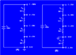
here is an example :
32NE0106.GIF
Actually you are using voltage divider method>> voltage drop using resistor. . and of course dont go with general 1/4watt resistors, for this you will need little high watt resistance .. Keep one thing in mind if there is voltage drop your current will rise !!!
Dont wrry.. Try this if it doesnt works for you, you still have best the option- Go for 50 v transformer !!
If still there is any confusion then visit this page :-
h**p://***.tpub.com/neets/book1/chapter3/1-35.htm

Good Luck :)
 

I think you don’t get the idea. :cool: Do some experiments using a variable load for the above resistive divider. Check the results.
Look here for a quick simulation:
Voltage Divider
 

ok
i got your idea!!! what you are trying to say is the input volt. to load is proportional to input load resistance and load resistance may vary so the input 50 v wont be stable!!!
ok, try zener diode for clamping voltage above 50 volt!!!
otherwise go for 50v transformer :twisted:
---------------------------------------------------------------------------------------------
If one option Fails i will give you another to try!!! :D
Good Luck :)

---------- Post added at 16:11 ---------- Previous post was at 15:13 ----------

Did a Li'l research. . [came to know input voltage will vary(if i am not wrong) !!!]

Go for 50 v transformer !!!
Good Luck :)
 

That is completely wrong!

The reason for not using a potentiometer is simply that it's not the right part to use. In any circuit where current passes through a resistor there will be a voltage drop. The drop depends on how much current so trying to stabilize the voltage at 50V is not possible unless the current is known and is constant. A potentiometer is even worse than a single resistor for two reasons, the track forms a potential divider in which the lower voltage section just wastes power and because the voltage dropped may only be over a short section of the track it cannot utilize the full power rating of the component.

The correct circuit is 220V AC to the transformer, 50V AC from it, a rectifier (possibly a bridge rectifier), reservoir capacitors and then either a linear or switch mode regulator to stabilize the output at 50V DC up to maximum load current.

Brian.
 

Status
Not open for further replies.

Similar threads

Part and Inventory Search

Welcome to EDABoard.com

Sponsor

Back
Top