Welcome to our site! EDAboard.com is an international Electronics Discussion Forum focused on EDA software, circuits, schematics, books, theory, papers, asic, pld, 8051, DSP, Network, RF, Analog Design, PCB, Service Manuals... and a whole lot more! To participate you need to register. Registration is free. Click here to register now.
EN1 = high always
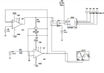
MR goes low when U2(+) exceeds 2V switching on Q1 to dump C Voltage and then (+) goes low , then counting is Reset.
I think MR needs to be inverted.or counter disabled with EN1=0 until counter is read, then do reset Q1 and MR=1
not sure where you got design, I did not verify completely, but I recall Labs using RCA app notes that had errors in a staircase generator I had to fix. Use logic to debug.
Sorry, but this design is incomplete. ADC needs 2 signals clock and strobe data. After data is read in, the strobe can go low to reset counters and start another conversion. A state latch is needed to disable counter and tell MPU, data is ready.
Another method is to handshake Start conversion from MCU and then wait for Data Ready. which disables counter. (EN)
In this design when U1out>2V , counter should be stopped, not reset.
This design wont work
it resets the counter, rather than drop EN. you can't control when this happens.
So add a signal to start conversion and , then reset Q1 , counter and enable counting for next conversion. It will then latch data by stopping counter when done.
Can you do me favor if u could design it again as you said so that will be easy to understand.. but initially it helped little bit to understand some how this adc can be implemented tnx!
Try again. Draw the signals and note what should happen, then design it with extra FF and control signal.
....So add a signal to start conversion and , then reset Q1 , counter and enable counting for next conversion using a monopulse.
It will then latch data by stopping counter when done with EN. You have two EN inputs.
Also choose f clock for desired max rate of VEE and RC ramp to +2V
This site uses cookies to help personalise content, tailor your experience and to keep you logged in if you register.
By continuing to use this site, you are consenting to our use of cookies.