Continue to Site

Welcome to EDAboard.com

Welcome to our site! EDAboard.com is an international Electronics Discussion Forum focused on EDA software, circuits, schematics, books, theory, papers, asic, pld, 8051, DSP, Network, RF, Analog Design, PCB, Service Manuals... and a whole lot more! To participate you need to register. Registration is free. Click here to register now.

[SOLVED] problem with sequential circuit

Status
Not open for further replies.

Centerpoint

Newbie
Joined
Jan 4, 2022
Messages
4
Helped
0
Reputation
0
Reaction score
0
Trophy points
1
Activity points
42
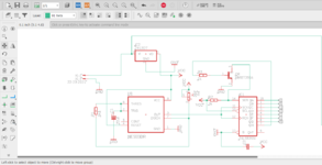
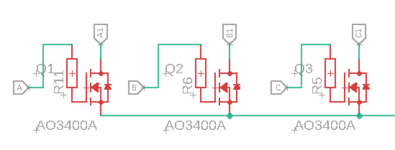
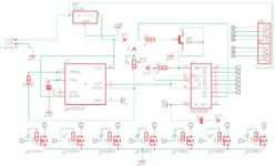
i need help regarding ic 74hc595. i have a circuit like in the picture i included. the main problem is when i connect it to the 12v adapter, the output becomes out of sequence, this circuit should work turning on the output from Q0,Q1 to Q7.
some of the things I've done:
1. Provide a decoupling capacitor of 0.1uf and 1uf parallel placed at pins 16 and 8 on IC 74hc595.
2. provide a capacitor on the 7805 regulator according to the datasheet (0.33uf at input, 0.1uf at output)
3. add the RC circuit on pin 12 as in the article https://hstech.ro/HC595/
the load of this circuit is a neon flex lamp, the adapter used is 12v 5A. I have printed this circuit on the pcb.
can anyone give me advice so that the circuit can run normally.
 

Attachments

  • schematic.png
    schematic.png
    52.8 KB · Views: 167
  • mosfet.png
    mosfet.png
    4.2 KB · Views: 158

Solution
There is even the questions are there any glitches on output of
555 timer clocking the 595. And if you attempt to slow down the
Tr and Tf into the 595 clock, that exposes it to noise related triggering,
an example below.

This sim is a ramp into simple CMOS input with 100 mV of noise on it.
Logic circuits do not like this, produces unstable states and switching.

So be careful about slowing down rise time on clock signals and inputs
in general.

1641302885179.png


Put your scope on infinite persistence, and look at power supply rails, clock inputs, to get an idea
of how much noise you have in system.

Not all caps, for equal capacitance, have the same ESR performance. Polymer Tants and ceramics,
combos of both, best in class. The Sanyo...
The intended circuit purpose isn't clear. HC595 has no defined power-on state, respectively the initial state and succeeding sequence shown by the circuit is arbitrary.
 

the purpose of this circuit is only sequential led, from the circuit I made, the output of the hc595 runs alternately from QA to QG, but the output is not a 5v led, but 12v. so I use a mosfet to drive the led.
when I turn it on, this circuit doesn't run sequentially. I am using AO3400A type mosfet, here is the complete schematic
 

Attachments

  • full.png
    full.png
    18.7 KB · Views: 149

There is even the questions are there any glitches on output of
555 timer clocking the 595. And if you attempt to slow down the
Tr and Tf into the 595 clock, that exposes it to noise related triggering,
an example below.

This sim is a ramp into simple CMOS input with 100 mV of noise on it.
Logic circuits do not like this, produces unstable states and switching.

So be careful about slowing down rise time on clock signals and inputs
in general.

1641302885179.png


Put your scope on infinite persistence, and look at power supply rails, clock inputs, to get an idea
of how much noise you have in system.

Not all caps, for equal capacitance, have the same ESR performance. Polymer Tants and ceramics,
combos of both, best in class. The Sanyo OS-CON is polymer technology. Many manufacturers now.

Imp_vs_f.gif


Regarding choice of regulator, keep in back of your mind to read carefully
output bypassing constraints. Some LDO regulators (your is not one of them),
have limits on output allowed min ESR. This is just a caution for future work.


Regards, Dana.
 
Last edited:

Solution
what are you powering the hc595 with?
the data sheet I found says maximum 6 V. the 7812 regulator puts out 12 V

you said the output was out of sequence.
what did you expect and what did you get?

as i see your circuit, IF, at power up , QA through QH are low (hopefully)
then at the first clock of the 555, QA will go high
as each clock passes, the QA goes to QB, etc and QA is again loaded high
QH is not high until the 8th clock, when on the ninth clock, QA will go low.

what you have is a gadget that runs a set of 8 zeros the 8 ones and continues
as 0 and 1 in groups of 8.

NOTE: i assumed all outputs low at power up
there is no guarantee that that is what happens.
if QA through QH are arbitrary on power up, the sequence of your neon flex lamps
(or are they LEDs?) will also be arbitrary, and likley not repeatable.
 

Here is example done with Arduino Nano board I think will work.

So you just need this board and the MOSFETS and gate R's. Eliminate the 555 and the
595.

Coding done with mBlock, you drag and drop blocks and mBlock converts that
to Arduino code, basically C/C++ code, for you.

1641311285901.png


Note when Arduino starts up all its outputs effectively tri state so MOSFET gates floating.
An R to ground should be done at each MOSFET gate input, to insure they startup off. Say 10K.
R from Arduino to gate ~ 1K or less.

Rate of LED cycles is set at 1 sec, you can set that to whatever you want.

iu


Nano is like a $3 board.

Note if you wanted trivial to add a test for low voltage to put a different
pattern on LEDs. Also trivial to add a test button that turns on, or off,
all LEDs. Or other logical triggers/patterns. And note timing much more
accurate than 555 timer.

So keep this in mind for future projects.

Regards, Dana.
 
Last edited:


Is that the pattern you are looking for ?

If interested I can post the project so you can open mBlock and look at it.

I set this for .5 sec LED to LED time. This of course is low current LEDs so I
can drive directly with Nano board. You would add the MOSFETS and R's
associated wit them to do your high current design.

Here is the block code that did the design -

1641331621030.png


Regards, Dana.
 

View attachment 173711

Is that the pattern you are looking for ?

If interested I can post the project so you can open mBlock and look at it.

I set this for .5 sec LED to LED time. This of course is low current LEDs so I
can drive directly with Nano board. You would add the MOSFETS and R's
associated wit them to do your high current design.

Here is the block code that did the design -

View attachment 173712


Regards, Dana.
yes, this pattern is absolutely true. unfortunately I use the clock from the ic 555, because I have printed the pcb, but thanks for the answer
 

There is even the questions are there any glitches on output of
555 timer clocking the 595. And if you attempt to slow down the
Tr and Tf into the 595 clock, that exposes it to noise related triggering,
an example below.

This sim is a ramp into simple CMOS input with 100 mV of noise on it.
Logic circuits do not like this, produces unstable states and switching.

So be careful about slowing down rise time on clock signals and inputs
in general.

View attachment 173708

Put your scope on infinite persistence, and look at power supply rails, clock inputs, to get an idea
of how much noise you have in system.

Not all caps, for equal capacitance, have the same ESR performance. Polymer Tants and ceramics,
combos of both, best in class. The Sanyo OS-CON is polymer technology. Many manufacturers now.

Imp_vs_f.gif


Regarding choice of regulator, keep in back of your mind to read carefully
output bypassing constraints. Some LDO regulators (your is not one of them),
have limits on output allowed min ESR. This is just a caution for future work.


Regards, Dana.
Yes, I haven't done the analysis using an oscilloscope, because I don't have one,
 

yes, this pattern is absolutely true. unfortunately I use the clock from the ic 555, because I have printed the pcb, but thanks for the answer
Not a problem, example done to show you alternative ways of getting lower
part count designs, more flexibility, better power cycling behavior, and ones
with more accurate clocks than the old 555 timer. Consider for newer designs.

Also if you are new to processors graphical block programing methods quite
visual/intuitive. If you know how to use a 4 function calculator you are already doing
some of this, like adding a set of numbers, the keystrokes procedures and methods
you have in your head. And they allow you to look at C/C++ code they generate
from your block design to gain a little bit of familiarity with more "normal" coding.
Lots of videos, many block programming variants, learn one you become already
quite comfortable with the others as they have many common blocks.

Many many videos showing how to start.


Regards, Dana.
 

Status
Not open for further replies.

Part and Inventory Search

Welcome to EDABoard.com

Sponsor

Back
Top