rallysteve
Newbie level 6
I am trying to develop a serial link over 868Mhz using two 89C51s (one at each end) I have got a simple piece of code allowing me to send a piece of 8-bit HEX data from my computer to the transmitter which in turn then sends to the receiver turning on a LED at certain values, and off at others, the HEX data is then returned to the PC via a second serial port. This works perfectly when connecting transmitter and receiver via a wire (between TXD and RXD pins using the UART) however when i connect my FM transmitter / receivers I am not able to receive anything. I think this is something to do with the transmitter side, and possibly the baud rate??
I am using 11.0592MHz crystals at both ends with the UART running in mode 1, with timer in mode 2. Following the application note i have set up for operation at baud rate of 9600. However I believe that the transmitter/receiver I am using has a max data rate of 4600 kHz, so am I right in thinking this could be the problem?
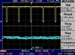
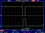
When connected the the oscilloscope the following pattern can be seen at the data in pin of my transmitter, with the
removed so that a constant series of data values are sent:

I have tried to reduce the baud rate of my transmitter by altering the TL1 reload value to #0F3H but it seems to make no difference to the frequency of the output measured on the ossciloscope which always shows 9.6kHz.
Is anyone able to help at all please??
I am using 11.0592MHz crystals at both ends with the UART running in mode 1, with timer in mode 2. Following the application note i have set up for operation at baud rate of 9600. However I believe that the transmitter/receiver I am using has a max data rate of 4600 kHz, so am I right in thinking this could be the problem?
Code:
$NOMOD51 						 ; Prevent Keil from defining SFR Registers
$INCLUDE (reg_c51.INC)
;
;
		ORG		000H
		LJMP 	BEGIN
;
;
		ORG		23H
		LJMP 	SERIAL_IT;
;
;
		ORG 	0100H
;
; Timer 1 in Mode 2 (8 Bits auto re-load timer)
BEGIN:
		MOV		SCON,#50H		 ; UART in mode 1 (8 Bit), REN = 1
		ORL		TMOD,#20H		 ; Timer 1 in Mode 2
		MOV		TH1,#0FDH		 ; 9600 Bds at 11.059Mhz
		MOV		TL1,#0FDH		 ; 9600 Bds at 11.059Mhz
		SETB	ES				 ; Enable Serial Interrupt
		SETB	EA				 ; Enable Global Interrupt
		SETB	TR1				 ; Timer 1 Run
;
		JMP		$				 ; Endless loop
;
;
SERIAL_IT:
		JNB		RI,EMIT_IT		 ; Test if it is a reception
		CLR		RI				 ; clear reception flag for next
		MOV		A,SBUF			 ; Move data from UART into Accumulator
		MOV		SBUF,A			 ; Send data from accumulator into UART
		CJNE	A,#00h,LED_ON	 ; Switch LED On
		CJNE	A,#0FFH,LED_OFF	 ; Switch LED Off
		LJMP	END_IT
;
;
LED_ON: CLR		P2.0
		RETI
;
;
LED_OFF:SETB	P2.0
		RETI
		;
		;
EMIT_IT:
		CLR		TI				; Clear transmission flag for next transmission
		;
		;
END_IT:
		RETI
		;

end
When connected the the oscilloscope the following pattern can be seen at the data in pin of my transmitter, with the
Code:
JNB RI,EMIT_IT ; Test if it is a reception
I have tried to reduce the baud rate of my transmitter by altering the TL1 reload value to #0F3H but it seems to make no difference to the frequency of the output measured on the ossciloscope which always shows 9.6kHz.
Is anyone able to help at all please??
