beaver
Junior Member level 1
bh1415
Hi guys,
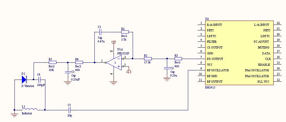
I am trying to build a frequency synthesizer using BH1415. The VCO and Phase Detector seem to work well. But when I add the loop filter, the loop cannot be locked. The schematic is shown in the picture.
My question is:
1, Can anyone tell me is there any fatal mistake in the circuit?
2, How can I build a good filter?
3, How to simulate the performance of a PLL?
Hi guys,
I am trying to build a frequency synthesizer using BH1415. The VCO and Phase Detector seem to work well. But when I add the loop filter, the loop cannot be locked. The schematic is shown in the picture.
My question is:
1, Can anyone tell me is there any fatal mistake in the circuit?
2, How can I build a good filter?
3, How to simulate the performance of a PLL?