Continue to Site

Welcome to EDAboard.com

Welcome to our site! EDAboard.com is an international Electronics Discussion Forum focused on EDA software, circuits, schematics, books, theory, papers, asic, pld, 8051, DSP, Network, RF, Analog Design, PCB, Service Manuals... and a whole lot more! To participate you need to register. Registration is free. Click here to register now.

Problem regarding dynamic resistance of Diode

Status
Not open for further replies.

neeraj786

Newbie level 5
Joined
Dec 21, 2011
Messages
8
Helped
0
Reputation
0
Reaction score
0
Trophy points
1,281
Activity points
1,340
how to calculate a dynamic resistance of a diode(Silicon) if i apply a sinusoidal wave (5V @ 20 HZ) and a resistance of 220 ohm is connected serially with diode ????
 

AC makes things complicated.

Here is the way to calculate it with DC. (The peak of 5 VAC is 7.07 V DC.)

Subtract the diode drop. (Common practice is to use 0.6V, although a typical range is 0.4 to 0.8 V for 1N400x series.)

Assume the resistor is by itself. Calculate current through it.
( 7.07 - 0.6 ) / 220 = 29.4 mA

The identical current is going through the diode.

Therefore diode resistance is V / A.
0.6 / .0294 = 20.4 ohms

Its dynamic resistance will vary throughout a sine cycle. Between 20.4 ohms and infinity. That is through one half of the cycle. During the other half it is not conducting.

If you desire accuracy, then do further iterations. Recalculate the diode drop between iterations.
 
  • Like
Reactions: neeraj786

    neeraj786

    Points: 2
    Helpful Answer Positive Rating
    V

    Points: 2
    Helpful Answer Positive Rating
AC makes things complicated.

Here is the way to calculate it with DC. (The peak of 5 VAC is 7.07 V DC.)

Subtract the diode drop. (Common practice is to use 0.6V, although a typical range is 0.4 to 0.8 V for 1N400x series.)

Assume the resistor is by itself. Calculate current through it.
( 7.07 - 0.6 ) / 220 = 29.4 mA

The identical current is going through the diode.

Therefore diode resistance is V / A.
0.6 / .0294 = 20.4 ohms

Its dynamic resistance will vary throughout a sine cycle. Between 20.4 ohms and infinity. That is through one half of the cycle. During the other half it is not conducting.

If you desire accuracy, then do further iterations. Recalculate the diode drop between iterations.

" But this resistance is not fixed ... it will vary .. suppose at pi/4 the amplitude of signal will different so resistance will also different.. so we can not say that it will vary from 20.4 ohm to infinity ...( 20.4 ohm resistance came when u consider 5V . and it will be different at different phase angle??? Is it Right?? """
 

Dynamic resistance is normally measured with a small AC signal riding on top of a forward DC bias. It varies with the DC bias.

Thus, for example, you could put 10mA DC through the diode with a small AC signal (such as 0.1mA) on top and measure the AC voltage (Vac) across the diode. The dynamic resistance would then be Vac / 0.1mA (at 10mA DC). If you measure at a different DC bias you will get a different dynamic resistance value.
 

Yes, diode resistance will be different at different times on the AC sinewave.

You can choose any point in the cycle you wish.
You would calculate the applied voltage on the sinewave.
Then you would derive the diode resistance using the above process.

Or to find the average resistance, you can:
(1) divide the sinewave into many equal steps
(2) calculate the applied voltage at each step
(3) calculate the corresponding diode resistance (using the above process)
(4) average all the values.
 

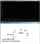
Let such calculation be performed by a SPICE simulation program. In case of a 1N4148 diode you can see the result here:
 

The results using the DC voltage across the diode as shown in erikl's post generates the apparent resistance, which includes the DC drop, not the dynamic resistance, which only measures the AC drop. To get the dynamic resistance you can do an AC simulation with a DC bias current through the diode (see below). For a 1N4148 the dynamic resistance varies from about 46Ω @ 1mA DC bias current to about 5Ω @ 10mA DC bias current.

Diode Resistance.GIF
 

The results using the DC voltage across the diode as shown in erikl's post generates the apparent resistance, which includes the DC drop, not the dynamic resistance

Right, crutschow! Now - with the same transient simulation data - and the exact circuit setup from the OP :

sinusoidal wave (5V @ 20 HZ) and a resistance of 220 ohm is connected serially with diode
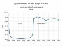
... I got this diagram for the differential resistance, calculated for voltage/current differences at time differences of 100µs :


There is a very old method of determining dinamic or differential resistance. It is graphical method. As crutschow described method to measure AC voltage drop with superimposed AC current on DC current for working point you can use V-I curve of diode and place tangent to different points on curve. Slope of tangent is directly equal to dinamic or differential resistance of diode in specific Vdc-Idc point.
 

(3) calculate the corresponding diode resistance (using the above process)
(4) average all the values
and get a meaningless number...

Dynamical resistance is a small signal quantity only valid for a particular diode current. Averaging might be useful for small variations, but not in the present case.

You get a serious problem in averaging when the dynamical resistance is about infinity for half of the cycle, by the way.
 
  • Like
Reactions: LvW

    LvW

    Points: 2
    Helpful Answer Positive Rating
Status
Not open for further replies.

Similar threads

Part and Inventory Search

Welcome to EDABoard.com

Sponsor

Back
Top