Continue to Site

Welcome to EDAboard.com

Welcome to our site! EDAboard.com is an international Electronics Discussion Forum focused on EDA software, circuits, schematics, books, theory, papers, asic, pld, 8051, DSP, Network, RF, Analog Design, PCB, Service Manuals... and a whole lot more! To participate you need to register. Registration is free. Click here to register now.

Preventing MOSFET from blowing on motor controller

Status
Not open for further replies.

mvoltin

Junior Member level 1
Joined
Jun 1, 2014
Messages
19
Helped
0
Reputation
0
Reaction score
0
Trophy points
1
Activity points
300
Need an advice to prevent the MOSFET from blowing up on a motor controller. Below is more info with little background:

After spending days reading online about different controller designs, I have given up the aspiration of figuring out how these things work. Just trying to get a scooter working so that my kids can ride it and be done with it. This is for a scooter with 250watt motor and the controller is a Chinese cheap stuff with variable throttle from a hall effect sensor. My 10 year old was driving it uphill and that is when it busted (MOSFET is blown and it is on full power all the time). I am getting a replacement controller but it would be dangerous if this happened again and kids having no way to stop the scooter.

Controller is supposed to be a current limiting to ~10amps (250watt and 24v) but I suspect the motor was drawing too much current on uphill and the current limiting feature did not work. (P.S. I ruled out motor running as a generator and sending current back to the controller as the cause since 1) it was during an uphill and 2) motor does not turn when the scooter is rolling, the chain can only "pull").

Right now, I am trying to figure out if, once i get a replacement, I can add some diode or something else to the controller to help prevent this from happening. Attached is the picture and partial diagram (only parts close to the MOSFET) since the overall controller is too complicated for me to draw. Couple clarifications about the diagram picture:

The drawing tool had limited library and the following components are substituted:

1) the NPN transistor on the schematic is actually a Schottky Rectifier - stps2045ct
2) Mosfet is 75NF75b
3) the two diodes on the left are actually 3 pin diodes BZX84C12V
4) and there is an IC:"339 st gz1k338" on the board that I think is a Low-power quad voltage comparator LM339

I know this is a very limited info but is there anything I can add/solder to this board that would prevent the MOSFET from blowing because of the high current?
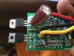
IMG_2473.JPG

Capture.JPG
 

Those mosfets appear to have white thermal grease on them. Were they on heat sinks?
Even if they were, a loss of contact could result in them overheating.

Did you try experimenting with a lesser power supply voltage, or lesser loads, to find out whether overheating starts to happen?
 

What is motor resistance and what model is chip controller?
 

There's possibly no other "chip controller" than a LM339. It's sufficient to make a triangle generator and pwm comparator.

It's relative difficult to analyse the design from hearsay. Having good photos from both PCB sides would allow to identify at least the topology.

An essential point would be to find out if the circuit implements some kind of overcurrent or stall detection. If so, there must be a sense resistor.

If the circuit doesn't have any kind of protection, you probably must accept that it's an (more or less) unsafe design which can't be easily improved.
 

It is also possible that the heat sink insulation failed; and somehow the heat sinks made contact with each other. It is also possible that the MOSFETs are still ok.
 

Hi Brad, the MOSFET and the diode were attached to the aluminum casing and the casing was acting as a heat-shield. The contact seemed pretty good when I opened the case... I have not experimented with the lesser power supply voltage but I know that it also has a low-voltage protection and will not work if voltage is less than ~21 - so, I do not have much room to play.

I appreciate the input but at this point, it may be too difficult for me to simulate different load settings, etc. (both technically and time-wise) - will probably just try to buy a more expensive controller and cross the fingers that it has the right overcurrent protection, etc.

Those mosfets appear to have white thermal grease on them. Were they on heat sinks?
Even if they were, a loss of contact could result in them overheating.

Did you try experimenting with a lesser power supply voltage, or lesser loads, to find out whether overheating starts to happen?
 

The wires are hiding the controller chip. I too have a china made controller of similar design (but not same) but I have not used it much. If you can post the controller number (take a picture with the wires out of the way) perhaps we can say more.
 

I could not find a current sensing resistor unless it is soldered on the board and I missed it when tinkering with a multimeter. Based on your response, I realize that this is over my head (probably the juice is not worth the squeeze at this point) and will be much easier to get a more expensive controller - although, some day hope to build one myself just for fun. Thank you for your time and trouble.

P.S. I initially thought that the 3 pin parts on the bottom left of the picture (Q4 and Q5) were the transistors and they helped with the current control (and a current sensing resistor somewhere there that I could not find) - this would have made sense. But, despite them being identified with "Q" for transistor, datasheets show these to be diodes (BZX84C12V) because of "Y2" and "Y3" markings on them... Anyway, thanks again.

There's possibly no other "chip controller" than a LM339. It's sufficient to make a triangle generator and pwm comparator.

It's relative difficult to analyse the design from hearsay. Having good photos from both PCB sides would allow to identify at least the topology.

An essential point would be to find out if the circuit implements some kind of overcurrent or stall detection. If so, there must be a sense resistor.

If the circuit doesn't have any kind of protection, you probably must accept that it's an (more or less) unsafe design which can't be easily improved.
 

The current sensing resistor must be the one with the large size: it is likely to have small value and you can see think pcb tracks going to it and connected in series with the motor connection. One end is very likely to be connected to ground.
 
  • Like
Reactions: FvM

    FvM

    Points: 2
    Helpful Answer Positive Rating
Current sensing resistor is on PCB back, conecting source of a MOSFET to black wire to minus battery. Signal is colected by R4 and sent to controller.
 

Current sensing resistor is on PCB back
No, I think the thick wire between source and black cable is the shunt.

We are still missing significant photos. Won't need to guess about parts on the bottom side ...
 

Need an advice to prevent the MOSFET from blowing up on a motor controller. Below is more info with little background:

After spending days reading online about different controller designs, I have given up the aspiration of figuring out how these things work. Just trying to get a scooter working so that my kids can ride it and be done with it. This is for a scooter with 250watt motor and the controller is a Chinese cheap stuff with variable throttle from a hall effect sensor. My 10 year old was driving it uphill and that is when it busted (MOSFET is blown and it is on full power all the time). I am getting a replacement controller but it would be dangerous if this happened again and kids having no way to stop the scooter.

Controller is supposed to be a current limiting to ~10amps (250watt and 24v) but I suspect the motor was drawing too much current on uphill and the current limiting feature did not work. (P.S. I ruled out motor running as a generator and sending current back to the controller as the cause since 1) it was during an uphill and 2) motor does not turn when the scooter is rolling, the chain can only "pull").

Right now, I am trying to figure out if, once i get a replacement, I can add some diode or something else to the controller to help prevent this from happening. Attached is the picture and partial diagram (only parts close to the MOSFET) since the overall controller is too complicated for me to draw. Couple clarifications about the diagram picture:

The drawing tool had limited library and the following components are substituted:

1) the NPN transistor on the schematic is actually a Schottky Rectifier - stps2045ct
2) Mosfet is 75NF75b
3) the two diodes on the left are actually 3 pin diodes BZX84C12V
4) and there is an IC:"339 st gz1k338" on the board that I think is a Low-power quad voltage comparator LM339

I know this is a very limited info but is there anything I can add/solder to this board that would prevent the MOSFET from blowing because of the high current?

View attachment 125825

View attachment 125771

It will be difficult to find the cause of the failure. If it was due to high drain voltage then there would have been symptoms of cracked case or black marks on the mosfet. It is very much likely failure from high current and heat.
If you replace the mosfet with another one that can take more current then you reduce the risk of repeat. You can use STP310N10F7 (100V, 180A) or something similar that you can source locally.
When the battery voltage drops to 12V the drive to the mosfet gate can drop to 6V and that will cause the mosfet to get hot and damage. If you add a voltmeter or a LED that indicates battery voltage below 18V, also teach your kids to observe that. That may prevent future failure.
 

Hi,
The controller should have (according to the specs) a low voltage cut-off at 20v and I am fairly certain the batteries were still charged well above 20 when this happened. Will certainly try to replace the mosfet with your recommendation but also will post additional info to see if I can figure the board out and prevent this from happening.

It will be difficult to find the cause of the failure. If it was due to high drain voltage then there would have been symptoms of cracked case or black marks on the mosfet. It is very much likely failure from high current and heat.
If you replace the mosfet with another one that can take more current then you reduce the risk of repeat. You can use STP310N10F7 (100V, 180A) or something similar that you can source locally.
When the battery voltage drops to 12V the drive to the mosfet gate can drop to 6V and that will cause the mosfet to get hot and damage. If you add a voltmeter or a LED that indicates battery voltage below 18V, also teach your kids to observe that. That may prevent future failure.

- - - Updated - - -

I just got another controller that is rated as 350watts and had much bigger case (I assumed it would be better build with more components, etc.) but, upon opening the case, it just seems an empty shell with a tiny board inside – same as the 250watt version described here. Getting a decent controller remains an elusive target.

I am posting additional pictures and description and hope for the following end result:
1) Once we figure out the current limiting function, make it more robust and, potentially, build a new current limiting circuit on a separate adjacent board.
2) Replace the MOSFET with STP310N10F7 per vBase recommendation
3) Use better heatsink for the Mosfet and the Schottky Rectifier.

Hope this makes sense and please advise if you would recommend a different approach.

So, here is some additional info from the pictures:
R1 = 33ohms
R3 =10k
R4 = 1k
R4 is connected to the Source (in parallel with the battery negative terminal) and is has two branches on the other side:
1) Pin 8 (Inverting input, channel 3) of LM339 (https://www.ti.com/lit/ds/symlink/lm339-n.pdf)
2) C4 that in turn connects to Pin 12 (ground) of LM339.
The drain is directly connected to a motor negative lead (there is no shunt resistor) and to the A1 and A2 of Schottky Rectifier - stps2045ct. K is connected to a positive supply.

Hope this provides more info for figuring out the current limiting function than my initial post. Thanks in advance.
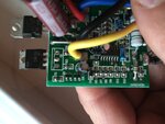
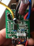
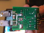
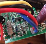
IMG_2505.JPG
IMG_2501.JPG
IMG_2497.JPG
FullSizeRender.jpg
FullSizeRender_1.jpg
 

IMG-2497 shows bad joint on the mosfet source, if it was always like that then it can produce enough heat to damage the mosfet.
If it's like that because you desoldered the pin then ignore this comment.
 

It may be the lighting on the picture but the actual connection of the source seems fairly solid and thick; I went back and looked at the board more closely after your comment.


What about the current limiting circuit, any suggestions where this maybe taking place? (Again, going on with a theory that the failure happened because the motor was trying to draw too much current and thinking of replacing the current limiting with my own circuit.)
 

1) AS a suggestion you can try putting two same part numbered MOSFETs as MOFETs can be put in parallel.
2) I am guessing on this the LM339 is being used as a comparator which would be generating the pulse for
based on the input from the throttle and Motor current.
3) There is a this metal wire between the MOSFET and other Chip, I think this is a current sense resistor rather than
a wire jumper.
4) One could make a simple PWM generator using NE555 and use it to drive a MOSFET for controlling the motor.
If one needs to implement over current protection one could use a current sensing resistor and use a comparator
to disable NE555 using pin4(on NE555) which is for RESET control.
5) One could use any N channel MOSFET like IRFZ44n or similar device.
 

Yes, the photos confirm that the current sense shunt is implemented as a piece of wire. The sensed voltage is fed to LM339 pin 8.

I think you can't easily determine if overcurrent respectively desaturation or e.g. excessive losses due to battery undervoltage are the cause of transistor damage. Replacing the transistor by a "stronger" type shouldn't be done without checking the switching waveforms. Q4/Q5 form a complementary gate driver, by the way.

I would start with sketching a complete schematic. The circuit connections can be best traced with a multimeter.
 

"Don't force it- just use a bigger hammer" - is most often the brute force solution that does not work in the long run.

You need to reverse engineer the schematic diagram. It will be rather easy to find out the net connections using a multimeter.

It should not be difficult to identify the resistors and capacitors. You are doing a post-mortem and you must not have a pre-conceived bias about the cause of the failure.

It would perhaps also help to take a hard look at the motor- if high current was the cause, there will be some remnant evidences still left.
 

Yes, the photos confirm that the current sense shunt is implemented as a piece of wire. The sensed voltage is fed to LM339 pin 8.

I think you can't easily determine if overcurrent respectively desaturation or e.g. excessive losses due to battery undervoltage are the cause of transistor damage. Replacing the transistor by a "stronger" type shouldn't be done without checking the switching waveforms. Q4/Q5 form a complementary gate driver, by the way.

I would start with sketching a complete schematic. The circuit connections can be best traced with a multimeter.


The reason I suggested a bigger hammer (mosfet) is because you are limited with choice. Let me explain.
The mosfet cannot limit the current like you do in linear power supplies because the mosfet is on a small heatsink and wont survive long. The only current limit is the resistance of the motor. If the resistance of the motor is say 1 ohm then at 24V you get 24A.
Your circuit current limit works by reducing the duty cycle to about 40% then the average current is about 10A, this saves the battery and keeps the motor and the mosfet from getting overheated.
There is a good chance that the circuit is badly designed and in some cases, due to switching loses, bad gate drive etc the mosfet breaks. Some of us experienced engineers will trace the circuit, probe a few waveforms and try to guess the reason for failure. The OP's choice is to buy a bigger driver board. It is hard to guide the OP how to analyze the circuit even if he has the circuit diagram.
A bigger mosfet with bigger dice can take more abuse hence survive better under most (not all) extreme conditions.
 

Status
Not open for further replies.

Similar threads

Part and Inventory Search

Welcome to EDABoard.com

Sponsor

Back
Top