Continue to Site

Welcome to EDAboard.com

Welcome to our site! EDAboard.com is an international Electronics Discussion Forum focused on EDA software, circuits, schematics, books, theory, papers, asic, pld, 8051, DSP, Network, RF, Analog Design, PCB, Service Manuals... and a whole lot more! To participate you need to register. Registration is free. Click here to register now.

Pre-conditioning analog signal for adc

Status
Not open for further replies.

Quantum Flux

Newbie level 4
Joined
Nov 14, 2012
Messages
6
Helped
1
Reputation
2
Reaction score
1
Trophy points
1,283
Activity points
1,325
I have been given a project for which I must use an ADC and other things. The ADC accepts 0-3VDC.

I have decided a co2 sensor will supply my analog signal. It needs 6v for a heating element and it supplies a signal of the range 30-50mV depending on c02 level. This must go through a buffer amp of course.

I'm trying to figure out how to make a circuit that would effectively adjust this range so I ultimately get 0-3V.

Can anyone point me in the right direction?
 

Use a noninverting opamp configuration with a gain of 3/0.05 = 60
 

Yes that will get my signal up to power, but I'm not sure the best way to trim out the 0-30mV range as it is wasted signal resolution.

I need to get a 30-50mV signal moved to 0-20mV.
 

Hello. Is the sensor supplied with 3VDC?

What does de output depend of? Is its variation linear?

You get a variation of 20mV, and the only thing you have to do is to move its 'zero' or eliminate its offset.

To do that you can use a non-inverting amplifier with a reference signal connected to the reference resistor (not the feedback one). The other way is to use two inverting opamps. Both ways will involve 2 op amps, because with the non-inverting amplifier needs a voltage coming from a buffer.

Another way to move its offset is with two resistors, depending of the ratio between them you will vary the offset being added.

That final voltage (between both summing resistors) must go to a high impedance (10 times the thevenin total resistance).

Then you should amplify the output voltage so it fits to the ADC referece voltages, which will increase the precision.

Hope being useful.

Bruno.-
 
The sensor is supplied with 6VDC for a heating element.
The CO2 reaction causes a differential of between 0-50mV on another set of terminals.
This must be fed through a buffer amp with at least 100G input impedance.
The thing is, the 0-30mV range is meaningless. Only 30-50mV is useful data.
So I need to chop off the 0-30mV range and end up with just 0-20mV. So 30mV in would give 0mV out and 50mV in would give 20mV out.
The relationship between C02 level and output voltage is approximately linear.
I tried putting an offset on my second opamp but the simulator is giving weird results (could be the sim).

Here is the sensor-
https://www.futurlec.com/CO2_Sensor.shtml
 

It seems to me your sensor actually outputs anywhere between 325mV down to 265mV, corresponding to 400ppm to 10000ppm of CO2.

Which part of this range are you interested in ?

Also the relationship is not linear - the ppm scale is log.

Or am I missing something ?

CO2 sensor curve.JPG
 
Yes, as kripacharya noted, it would appear that 30 to 50mV is the range of signal change going from around 265mV to a little more than 320mV. So you have much more offset to cancel then you stated.
 
I hadn't noticed the log scale, just the line. I see now that it is logarithmic.
Also I was confused between the graph showing hundreds of mV and the table showing 30-50mV.
I have sort of worked out a solution for the design now. The problem was the simulator on my iPad was wrong. I've modelled it in microcap now and it works. Thanks for all the help!
 

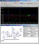
Note that only a few op amps have less than a pA of input current as required by your sensor. Below is a simulation of a circuit to perform the gain and offset using such an op amp.

C02 Amp.gif
 

Note that only a few op amps have less than a pA of input current as required by your sensor.
Did you see somewhere a sensor resistance specification?
 

Hi,

100G is not easy to achieve.
Even if you find an opamp with that input impedance you need to take care of every piece of wire, it's length and isolation, every solder joint has to be cleaned carefully and the traces on the pcb need careful routing.
If you really need thatyou may consider active shielding of your signals.

Klaus
 

It must be my eyes! Thank you.

In fact I expected something like this, but somehow didn't find the specification.
 

Status
Not open for further replies.

Similar threads

Part and Inventory Search

Welcome to EDABoard.com

Sponsor

Back
Top