Continue to Site

Welcome to EDAboard.com

Welcome to our site! EDAboard.com is an international Electronics Discussion Forum focused on EDA software, circuits, schematics, books, theory, papers, asic, pld, 8051, DSP, Network, RF, Analog Design, PCB, Service Manuals... and a whole lot more! To participate you need to register. Registration is free. Click here to register now.

[SOLVED] Power supply design for lowpower battery powered board

Status
Not open for further replies.

podoljano

Junior Member level 2
Joined
Oct 7, 2012
Messages
20
Helped
0
Reputation
0
Reaction score
0
Trophy points
1,281
Activity points
1,467
Hi guys i have a little design issue. I am designing a board that will include a gps/gsm module, aswell a uController theese will run at 3.3V.
my problem is that i am powering this system with a litium polymer battery that has a nominal voltage of 3.7 volt. I belive that the battery will not be able to have a stable voltage to power my system(so i belive - if im wrong please correct me), therefore i must use a low dropout voltage regulator. the lowest i was able to find is a 3.3V Vout with 0.1V dropout voltage. This means the battery discharge below 3.41-3.42 volt will not be used. I have not been able to find any good information about discharge graphs on theese batteries.
The question is: how is much battery capacity am i loosing in this design? - is there better ways to do it? i really try to avoid using switch mode though, since the space is really crowded, plus the noise it creates..

thanks in advance
Nikolaj
 

Nominal Voltage of Lithium Ion Batteries
https://www.bixmart.com/Nominal-Voltage-of-Lithium-Ion-Batteries_ep_54-1.html

BatteryDischargeChart.jpg


You can use schottky diode to lower voltage (voltage drop 0,2V). Use two in serie to drop 0,4V.
 

The discharge curve depends upon the rate of discharge. What is the battery capacity and the load you will draw from it?
 

thank you very much for the graph tpetar! but what do you mean with the shottky diodes? - i was planning to use the voltage regulator in order to stabilize the voltage(to avoid ripple and such, ofcause with a good cap aswell). crutschow the battery is labeld as 1200mAh, but its a cheap chineese one, so i guess 900-1000. for the current consumption i cant really tell since its a very dynamic system with sleep modes and on. However i predict the average draw would be in the range of 150mA. After posting this thread i decided to meassure it for myself, so im currently discharging the battery and meassureing the voltage drop over time. ill post the results when im done:)
 

thank you very much for the graph tpetar! but what do you mean with the shottky diodes? - i was planning to use the voltage regulator in order to stabilize the voltage(to avoid ripple and such, ofcause with a good cap aswell). crutschow the battery is labeld as 1200mAh, but its a cheap chineese one, so i guess 900-1000. for the current consumption i cant really tell since its a very dynamic system with sleep modes and on. However i predict the average draw would be in the range of 150mA. After posting this thread i decided to meassure it for myself, so im currently discharging the battery and meassureing the voltage drop over time. ill post the results when im done:)

Diode have voltage drop, for schottky diode is 0,2V and default rectifier diode is 0,7V. Do the simple test put diode in circuit and measure voltage after first diode, then after second diode with voltmeter.

You dont have ripple voltage on battery voltage. But ripple voltage can appear if you intermeddle with voltage regulators, specilly switcher types.

From 3,7V to 3,3V its very small voltage difference, you can see if some LDO regulator capable to do this job.
 
Last edited:

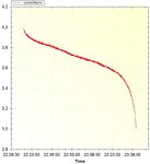
Okay so finally i had the time to finish my test. and the results are awesome, it seems that around 90-95% of battery's capacity is over 3.3V.
the voltage was meassured with a load of 15 ohms.
graph.JPG, thanks for all the help. im now pretty confident that ill choose a LDO with a 0.1V dropout and still have a good effeciency..
 

See this:

https://www.analog.com/en/power-management/linear-regulators/adp1706/products/product.html


Maximum output current: 1 A
Input voltage range: 2.5 V to 5.5 V
Low shutdown current: <1 μA
Low dropout voltage: 345 mV @ 1 A load
Initial accuracy: ±1%
Accuracy over line, load, and temperature: ±2.5%

16 fixed output voltage options with soft start: 0.75 V to 3.3 V (ADP1706)
16 fixed output voltage options with tracking 0.75 V to 3.3 V (ADP1707)
Adjustable output voltage option: 0.8 V to 5.0 V (ADP1708)
Stable with small 4.7 μF ceramic output capacitor
Excellent load/line transient response
Current limit and thermal overload protection

;-)
 

thats a nice one! however i found these: http://www1.elfa.se/data1/wwwroot/assets/datasheets/XC6210_eng_datasheet.pdf
&#56256;&#57049;FEATURES
Maximum Output Current : More than 700mA
(800mA limit, TYP.)
(1.6V<VOUT(T)<5.0V)
Dropout Voltage : 50mV @ 100mA
: 100mV @ 200mA
Operating Voltage Range : 1.5V ~ 6.0V
Output Voltage Range : 0.8V ~ 5.0V (0.05V increments)
Highly Accurate : +2%(The setting voltage accuracy)
Low Power Consumption : 35&#56257;&#56342;A (TYP.)
High Ripple Rejection : 60dB @1kHz

- This one seems really neat, epecially since its dropout voltage reduces when the current draw is reduced.. this basically means i can drive my circuit stable untill i reach a battery voltage of 3.41V, which means i will be able to use approx 80-90% of the battery capacity..
 

Status
Not open for further replies.

Part and Inventory Search

Welcome to EDABoard.com

Sponsor

Back
Top