Vermes
Advanced Member level 4
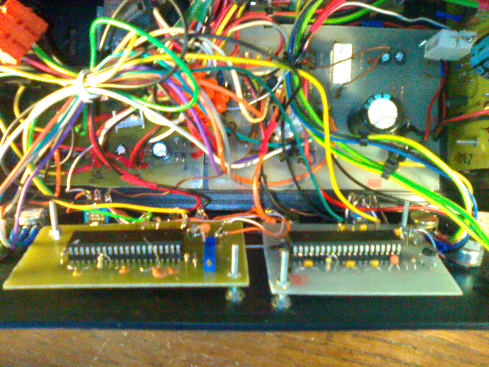
Presented here power supply consists of two pieces, based on popular project: LINK.
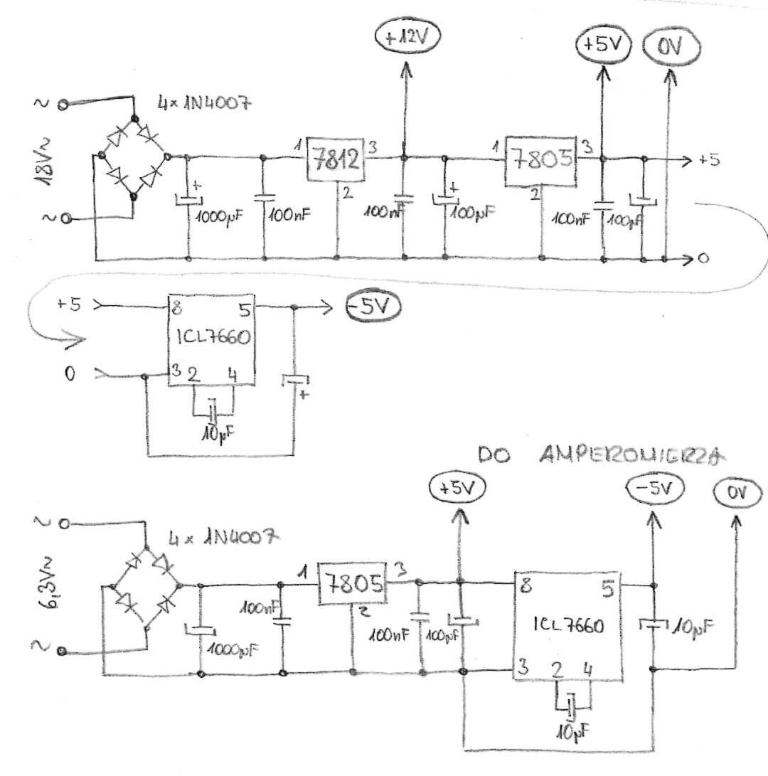
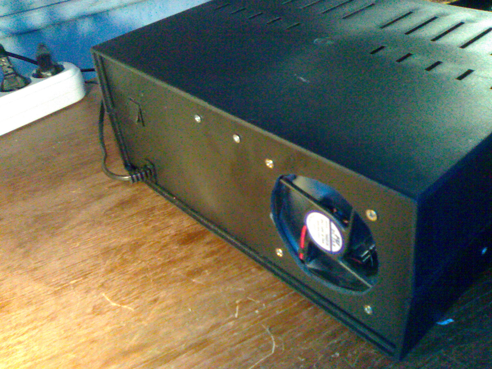
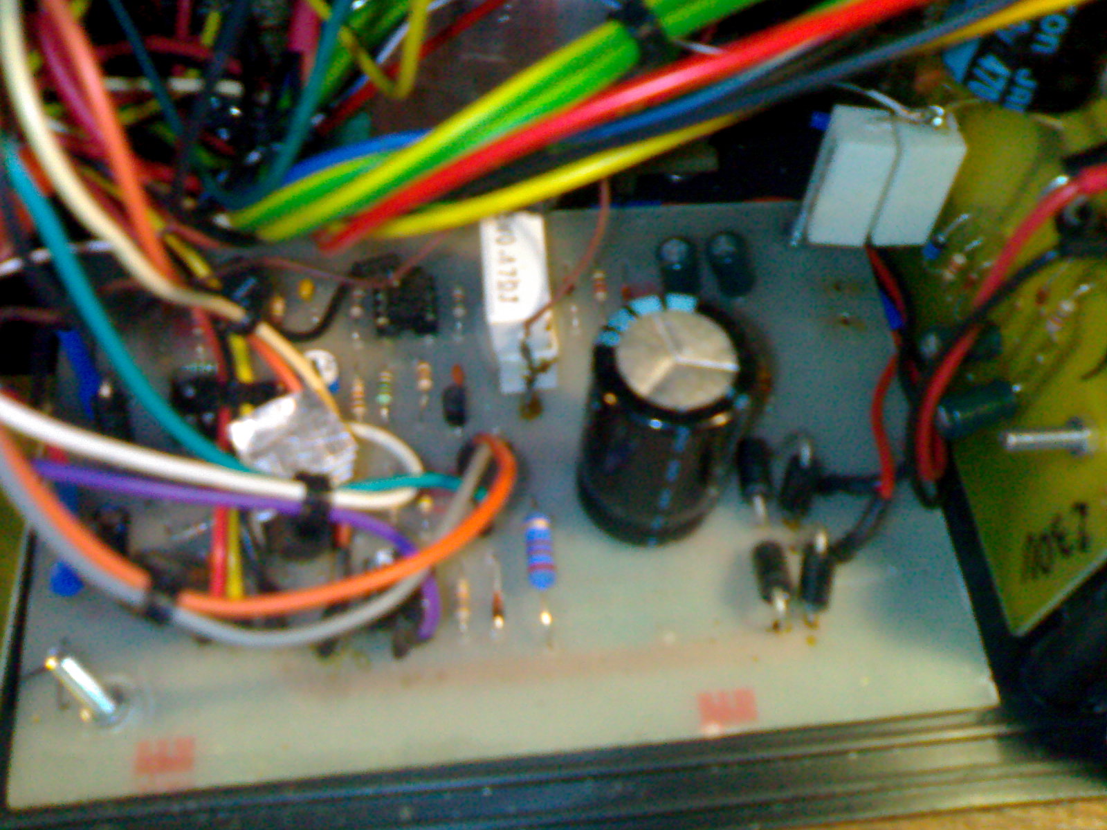
Transformer used was Unitra Ts90/16, because it has a lot of output voltages. Despite the fact that it powers two power supplies, that transformer also powers the board, from which voltages come out to the fan and meters - schematic of the board can be found below:
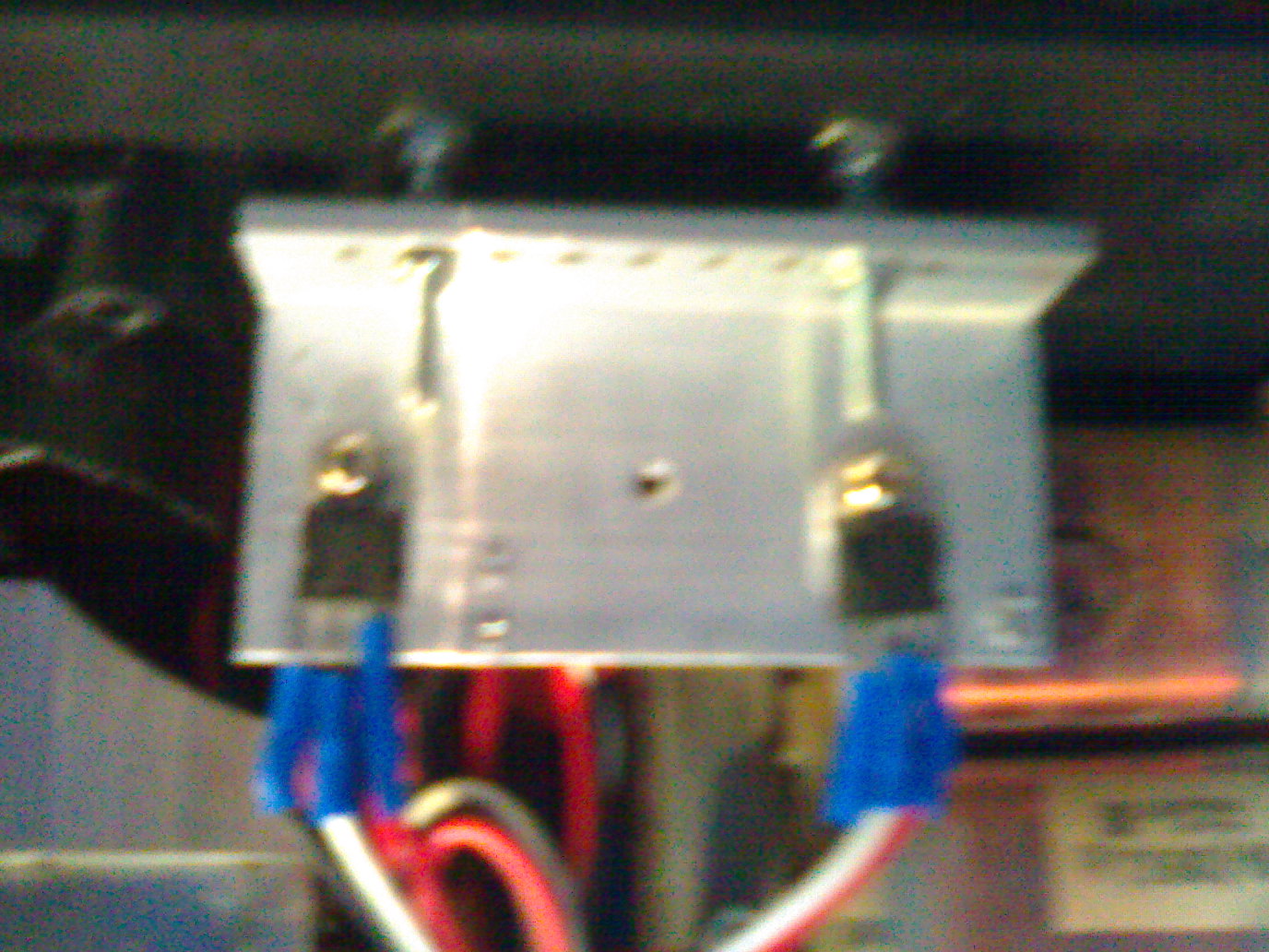
PCB ready for thermal transfer method:

Ready PCB:

The board gives voltages of: 12V, -5V, 0V, +5V, what allows for starting the fan, ammeter and voltmeter on ICL7107.
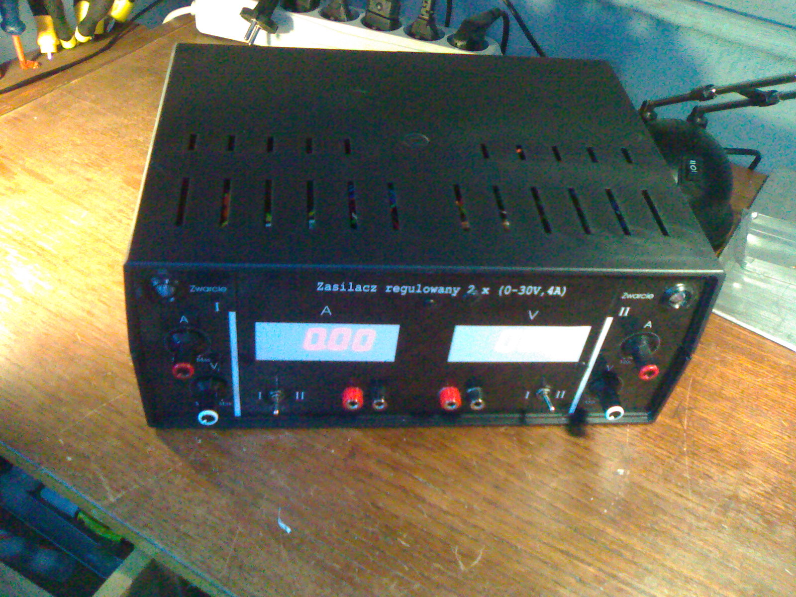
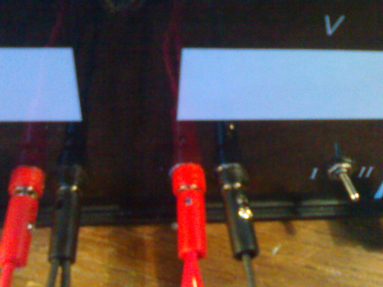
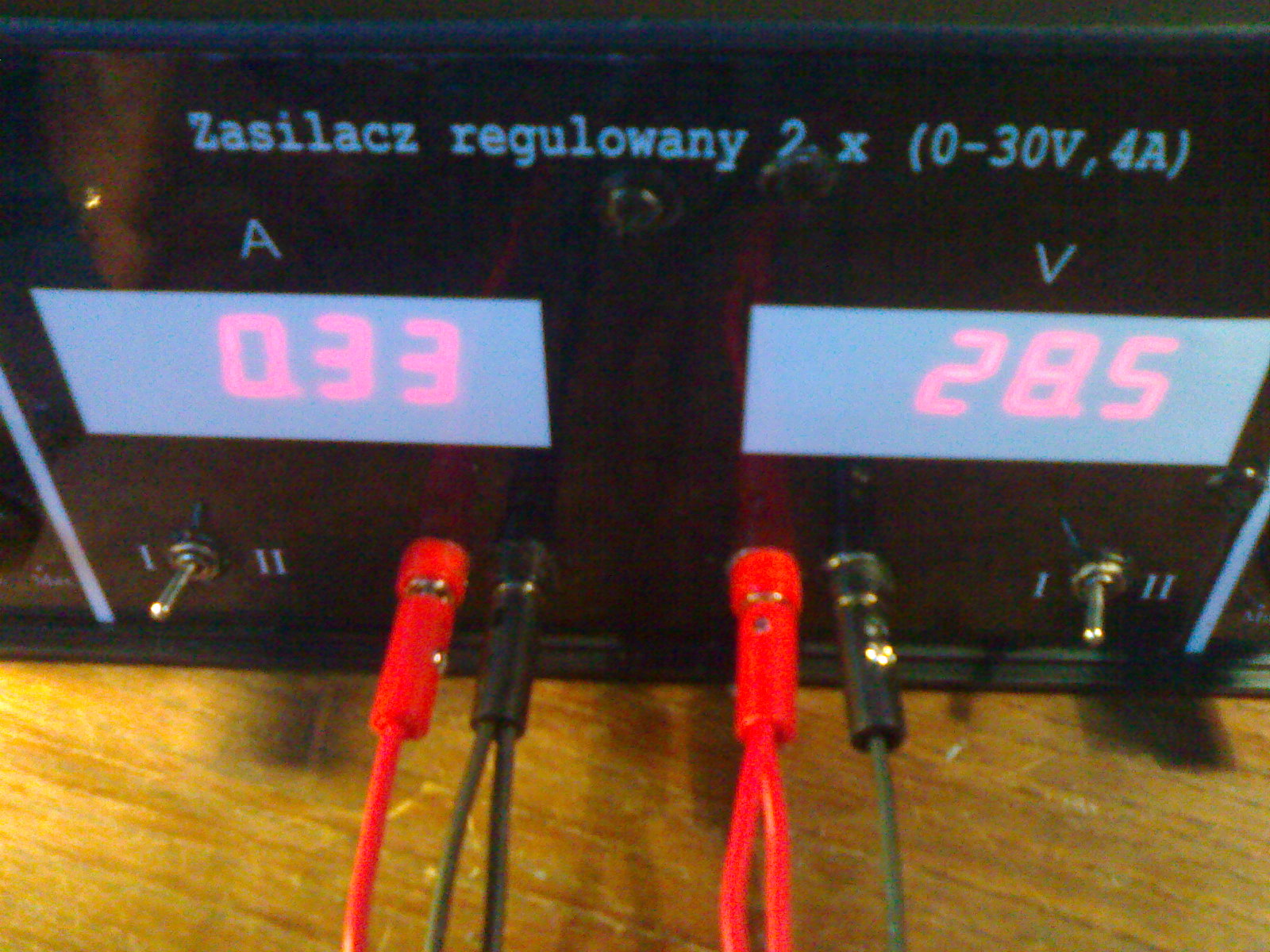
Power supply:
The power supply is fully adjustable, you can reach a voltage of -30V to 60V, you can also reach almost 8A at max 30V, or almost 60V at 4A. All that is available when you connect the cables properly at the output. To avoid making additionally two meters, there are switches – under the voltmeter there is a switch, using which you can change the measurement V power supply No. 1 or 2, the same with ammeter.
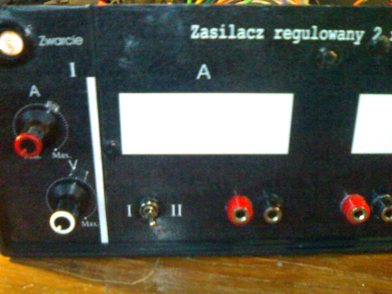
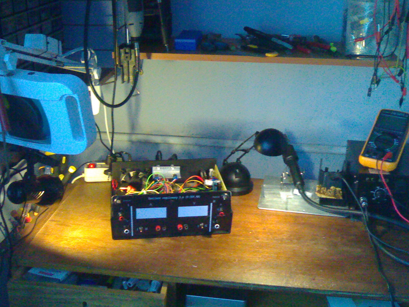
Panel:
The front panel was made in Corel, printed black on a laser printer t640, then laminated, cut and glued with a double-sided tape.
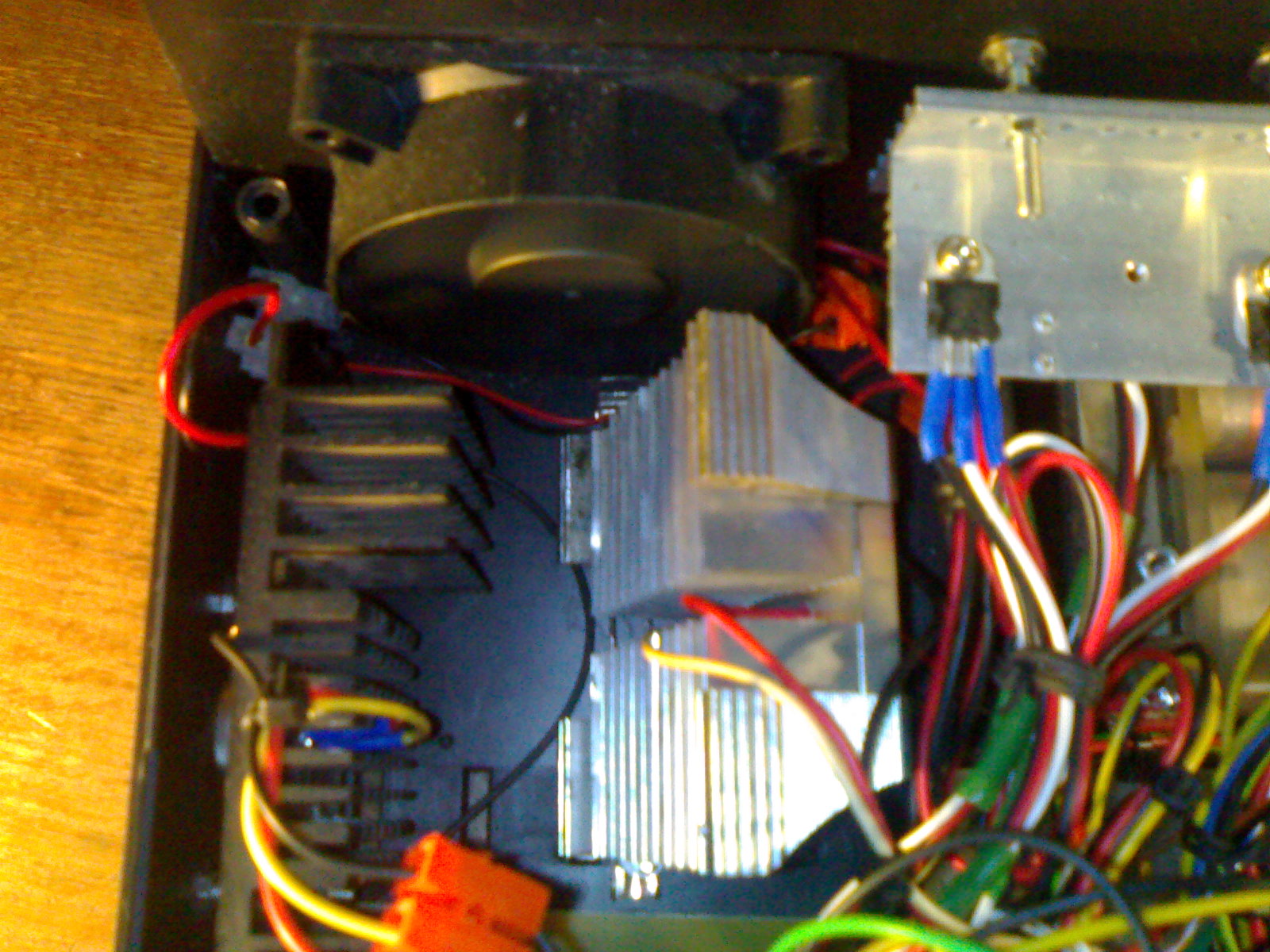
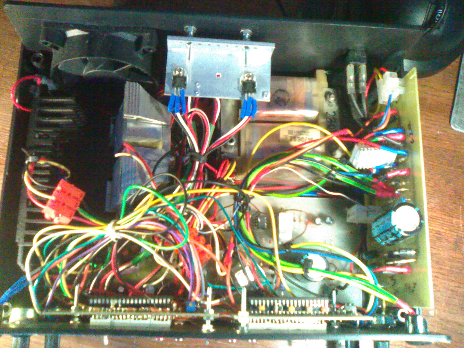
Pictures:


Link to original thread - Mój pierwszy DIY, Zasilacz 2 x (0-30V,0.01-4A)