Continue to Site

Welcome to EDAboard.com

Welcome to our site! EDAboard.com is an international Electronics Discussion Forum focused on EDA software, circuits, schematics, books, theory, papers, asic, pld, 8051, DSP, Network, RF, Analog Design, PCB, Service Manuals... and a whole lot more! To participate you need to register. Registration is free. Click here to register now.

Power an analog accelerometer 3V, from 48V Phantom Power

Status
Not open for further replies.
From the ADXL326 data sheet: current consumption 300uA ...
I'd use a resitor (say 1.5k) followed by a zener diode (between 8 and 12V) and then 3V linear voltage regulator with typicalllly associated components such as input/output capacitors ..
:wink:
IanP
 
From the ADXL326 data sheet: current consumption 300uA ...
I'd use a resitor (say 1.5k) followed by a zener diode (between 8 and 12V) and then 3V linear voltage regulator with typicalllly associated components such as input/output capacitors ..
:wink:
IanP

Good advice. Think this **broken link removed** would work as voltageregulator?

2nd problem. I can't find any min/max input voltage ratings for the Motu pre8, to know if i need a preamplifier for the output of the accelerometer.
I'm thinking it might be because there is some standard for it, and thats the reason they dont write it in the manual or tech notes.

Anyone know the answer to this?
 

I'm thinking it might be because there is some standard for it, and thats the reason they dont write it in the manual or tech notes.
Yes, it's a microphone input, typical signal levels are mV up to 100 mV. Very surely you don't have a problem of needing amplification.
 
So even with XLR cables of 3-4 meters i wont need any amplification?

- - - Updated - - -

Guess that depends on the bandwith... 20-500Hz, then i guess it wont be a problem.
 

48V to 3V.jpg

Think this would work?
 

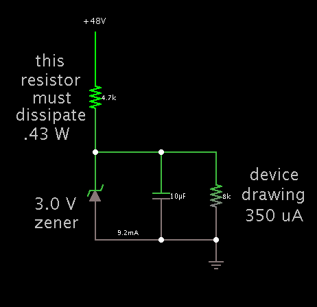
If the supply is just to power your device at 350 uA...

and it can work on between 1.8 and 3.6 V...

then you probably can get by with a 3V zener diode regulator.

Schematic:

99_1346621140.png
 
Yes, it's a microphone input, typical signal levels are mV up to 100 mV. Very surely you don't have a problem of needing amplification.
From this link it looks like Line In is 3.5V peak-to-peak
http://www.covingtoninnovations.com/audio/digitizing/index.html#levels

My accelerometer has a DC offset of Vs/2, and a sensitivity of 57mV/g. This means a DC offset on 1.5V and approximately +- 1V since is +-16g accelerometer.

This means i have to remove the DC offset from my accelerometer right?
 

From this link it looks like Line In is 3.5V peak-to-peak
Microphone isn't line level. A microphone input usually won't be able to process line level without overload respectively signal distortion.

The acceloremeter output would be AC coupled anyway, not to short phantom power. An asymmetrical connection (one line capacitively grounded, the other coupled to the signal) should work, for best rejection of interferences, professional equipment would utilize an audio transformer.
 

I suggested two ways:
- by capacitors
- by audio transformer

I guess you'll go for the first, it involves two capacitors.

The wikipedia schematic shows the mixer console side of phantom power.
 

Acc picture.png

This is what i figured out so far.

R1 & R2 is 6.8k resistors.

Followed by 3V zener regulatorcircuit.

I dont have the Motu Pre 8 yet, so im not able to test if this would work. Anyone can see any problems in this circuit?

Help is much appreciated.
 

The coupling capacitors have to be charged after powering or plugging-in the device. Hot-plug should be avoided, you'll better add overvoltage protection for the accelerometer output just in case. I presume that the mixer side is protected against 48V transients that can occur during possible hot plug events.
 
My output pins on accelerometer has maximumratings of Vs + 0.3V. So that would be 3.3V
Output from accelerometer is Vs/2 + 57mV*+-16g = 1.5V +- 1V.

Any better ways of protecting against overvoltage than the three zenerdiodes i have added here?
Accelerometer w protection.JPG
 

Basically not bad. I would perhaps place a series resistor (100 ohm or so) between z-diode and accelerometer output to provide additional current limiting for the pins.
 
Last question before this is hitting the PCB. All Common pins on the accelerometer, what to do with those?
I only need to connect 1 to ground as they propose in the datasheet? And then leave the rest hanging, or what do to?
 

I only need to connect 1 to ground as they propose in the datasheet?
The datasheet says NC pins 1 and 9 can be connected to ground.
 

I meant pin 3,5,6,7 called COM(common). In datasheet they propose connecting a decoupling from Vs to COM(connected to GND). But can i do this with just one out of the 4 COM pins, and leave the rest of them hanging? Or should i connect all 4 COM pins to GND?
 

Where do you see suggested in the datasheet to connect only one COM pin?

Power supply pins should be always connected completely. Otherwise correct chip operation isn't guaranteed.
 

The 3V supply for the accelerometer is working just fine. If i dont connect the Accelerometer X_output to the XLR pin 2, but just measure the voltage with ref to gnd. Then i get the right output from accelerometer. From 1.45V to 1.55V when i turn the accelerometer from -1G to +1G.

If i connect the accelerometer output to XLR pin 2, then i measure 7-8V at the output, and cant see any change when i turn the accelerometer. Am i doing something wrong?

New acc PCB.JPG
 

Status
Not open for further replies.

Similar threads

Part and Inventory Search

Welcome to EDABoard.com

Sponsor

Back
Top