Continue to Site

Welcome to EDAboard.com

Welcome to our site! EDAboard.com is an international Electronics Discussion Forum focused on EDA software, circuits, schematics, books, theory, papers, asic, pld, 8051, DSP, Network, RF, Analog Design, PCB, Service Manuals... and a whole lot more! To participate you need to register. Registration is free. Click here to register now.

Please explain how this op amp works( 2nd stage).

Status
Not open for further replies.

yonzzan

Junior Member level 3
Joined
Dec 12, 2006
Messages
26
Helped
0
Reputation
0
Reaction score
0
Trophy points
1,281
Activity points
1,522
11_1171609080.jpg

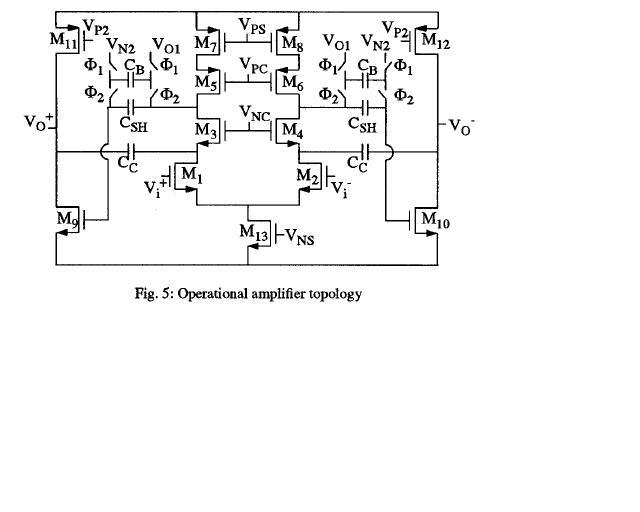
Can anyone explain how the second stage of this topollogy works? The first stage looks like a telescopic op amp but I am not sure about that as well. I have never seen this type of topollogy. I would also appreciate if you can let me know any text book covers this topology.

With much appreciation
 

I can't see the picture clearly. In my opinion, it's a two stage cascade amplifier. You can refer Razavi's Design of Analog CMOS Integrated Circuits.
 

it looks like a two differential amp cascaded together.
 

this is the folded cascode differential stage

For output swing to be larger this circuit is used.

The bottom transistor are supplying the current to the cascode stage

to meet high gain this kind of structure is used.
 

You can refer to the following paper.
A. R. Feldmann, B. E. Boser, and P. R. Gray, “A 13-Bit, 1.4-MS/s Sigma-Delta Modulator for RF Baseband Channel Applications,” in Proceedings Custom Integrated Circuits Conference, pp. 229-232, 1998

A potential problem is how to bias the 2nd input stage at low voltage level.
 

Hey yschuang,
I looked at the paper and found the topollogy. However, the second stage does not include the current tail transistor which my figure includes.
Does that change anything?
61_1171645573.JPG


Added after 4 minutes:

Can you explain what the difference between the circuit above and this one
91_1171326283.gif
 

the difference is that the frist one implements a level shifter using Csh.

Note that in your original circuit , the second stage is also fully differential, this means two CMFBs are required, one for each stage. but the circuit above (from razavi's book) can have only one CMFB.
 

Hi,

I do not think the 2nd stage needs another CMFB circuit because it is a pseudo amp.

Caps are used to do biasing.
 

Status
Not open for further replies.

Similar threads

Part and Inventory Search

Welcome to EDABoard.com

Sponsor

Back
Top