Continue to Site

Welcome to EDAboard.com

Welcome to our site! EDAboard.com is an international Electronics Discussion Forum focused on EDA software, circuits, schematics, books, theory, papers, asic, pld, 8051, DSP, Network, RF, Analog Design, PCB, Service Manuals... and a whole lot more! To participate you need to register. Registration is free. Click here to register now.

[SOLVED] Pin help ADS

Status
Not open for further replies.

57bel

Newbie level 5
Joined
Mar 5, 2019
Messages
10
Helped
0
Reputation
0
Reaction score
0
Trophy points
1
Activity points
89
Hello,
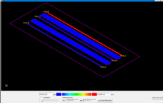
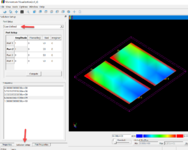
I am trying to model the coupling between three transmission lines each fed individually. I model it in momentum and get an output and a 3d model. It only shows one of the 3 lines being fed. In properties I have tried to change from in input output to input only or output only. I have tried making pins in schematic and all the lines and creating a layout over. No matter what it always has only Pin one being a feed, and the rest are all receiving. If anyone knows how to set a pin to output I would appreciate it!
 

Solution
By default, port 1 is excited. You can change that in the current viewer properties:
Go to the Solutions tab and change Port Setup to "User Defined", then you can specify amplitude and phase for all ports.

(Don't modify pin properties in layout, that has no effect on current viewer)
The coupling what you mean you can not see it? you want to visualize it?

...the effect of the coupling is calculated with momentum and the s parameters have been calculated with the coupling and it is accurate
 
The coupling what you mean you can not see it? you want to visualize it?

...the effect of the coupling is calculated with momentum and the s parameters have been calculated with the coupling and it is accurate
Hello, thanks for your reply! When looking at the 3d model (Momentum Visualization window) you can set the fields to see. When I model the coupling line I can only see the one line being used. Please see attached image. I was hoping to see all three lines illuminated and there to be coupling on the ground lines in between. If I am reading this wrong please let me know.
 

Attachments

  • ADS.PNG
    ADS.PNG
    42.5 KB · Views: 135

By default, port 1 is excited. You can change that in the current viewer properties:
Go to the Solutions tab and change Port Setup to "User Defined", then you can specify amplitude and phase for all ports.

(Don't modify pin properties in layout, that has no effect on current viewer)
 

Attachments

  • mom_vis_multiport.png
    mom_vis_multiport.png
    131.1 KB · Views: 132
Solution
By default, port 1 is excited. You can change that in the current viewer properties:
Go to the Solutions tab and change Port Setup to "User Defined", then you can specify amplitude and phase for all ports.

(Don't modify pin properties in layout, that has no effect on current viewer)
Thanks! That was exactly what I needed! It is working now.
 

Status
Not open for further replies.

Part and Inventory Search

Welcome to EDABoard.com

Sponsor

Back
Top