Continue to Site

Welcome to EDAboard.com

Welcome to our site! EDAboard.com is an international Electronics Discussion Forum focused on EDA software, circuits, schematics, books, theory, papers, asic, pld, 8051, DSP, Network, RF, Analog Design, PCB, Service Manuals... and a whole lot more! To participate you need to register. Registration is free. Click here to register now.

PID with STM32 for dummies tuning Ziegler-Nichols.

Coper

Member level 4
Joined
Mar 16, 2017
Messages
69
Helped
0
Reputation
0
Reaction score
0
Trophy points
6
Activity points
773
I would like to use PID to control the heating of the liquid.
I have about 3kg of liquid, a 16-bit temperature sensor and a 400W electric heater
I want to use the CMSIS PID from the DPS library as an algorithm.
For tuning, I should be fine with the Ziegler-Nichols method.


Maybe I'm stubborn, but tuning is not completely clear to me.

  • The system is cold temperature =20C, time zero, heating off.
  • I turn on the heater and measure the temperature every second.
  • After some time the temperature is 120C, at this temperature I turn everything off for safety reasons, it is 20% above the maximum working temperature, etc.
I can make a graph with time on the x-axis and temperature on the y-axis. I can read the dead time and the time constant tau from the graph.

I don't know what to do with
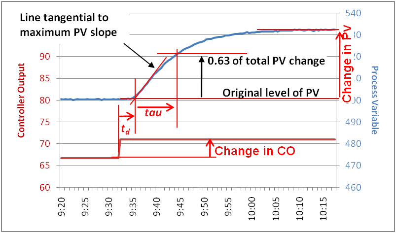
Calculate the process gain (gp) as follows:

gp = change in PV [in %] / change in CO [in %]“

My Controllel Output changed from off to on that's a 100% change, Process Value changed from 20C to 120C. I really don't know what the percentage change is, should it also be taken as a 100% change and gp=1 boost or what?
 
Sorry, the link to the Ziegler-Nichols method in the original post is broken, making the question less clear.

StepTest.png
 
Last edited:
"change in PV" used in the calculation is the steady state value. Has temperature already reached steady state in your experiment?
--- Updated ---

Process gain as percent value refers to temperature relative to full scale range.
 
Last edited:
I haven't reached a steady state, but a maximum safe state.
My reactor, which I heat with oversized heating.
The user adjustable temperature will be 100C with a five percent margin
a typical technologically used range of 65 to 95
120C is the range at which the thermal protection switches off.
I cannot reach a steady state when the heating power = heat loss is estimated to be 150C +-10C (my guess or rather impression), but that temperature would destroy or damage my thermal sensors.
>Process gain as percent value refers to temperature relative to full scale range.
Yes, that's what I basically don't understand
I understand that Ziegler-Nichols in 1942 solved this for pneumatic PID controllers with a range of 0-15 psi, but it should work in general and it is not possible for me to have different results when they used a thermometer with a range of -20 to 150 C and another with a thermometer of 0 to 1200C.
 
OK
I can do that in principle
HOWEVER, within the basic time frame, i.e. 1 second, I can't (don't want to) control the heating power other than On Off-
The original idea was. every second I will measure the temperature, count the PID with a possible result of 1 or 0 for the next second,
Regulation with a step of 10% is thus possible within a block of 10 seconds and with a step of 1% even 100 seconds
Such a slow regulation probably won't work very well.
What is the correct solution?My heating is 230V and I don't want to count waves
 
The available time resolution in full wave switching is 20 ms. For slow heating processes, cycle times of 1 to several 10 seconds are appropriate. Resolution can be however improved by integrating the error term (first order delta-sigma modulator).

Considering this option, you may get acceptable results with fixed 1 second on-off cycle. But there's surely a trade-off between laziness and performance.
 
I tried to get a more accurate idea of the situation based on a fairly primitive mathematical model and ran into a new problem (a problem that I didn't come across originally)
As we have already said, the heating has 400W ie, 400W/s ie 400J
to heat by 1K, I need 3500 to 7000J depending on how much "liquid" I heat.
Here comes the problem
what I'm heating is not a cold liquid, so at a certain point it melts and the heat is used to change its state
At maximum content, approx. 250 kJ is consumed, this is full heating without losses, it will run 250k/400 = 625 seconds.
from the point of view of the 625s graph I will tiut and theoretically the temperature will not rise and the whole concave function will be divided into two parts,What about that, do I have to cut out the part where the state changes to calculate the PID coefficients?
I will return to the issue of performance management in the evening
 
Ziegler-Nichols PID parameter optimization is assuming linear, time-invariant process what yours apparently isn't. PID controller is however fairly insensitive to process parameter variation. I would probably record transfer function in a region without state change and check if the respective PID parameters work also over state change.

Or, if you want to spend more effort, make a non-linear process model and evaluate the behaviour e.g. in Matlab/Octave.
 
Hi,

if I understand right, then the melting temperature is always below PID_SETPOINT temperature. In this case you may ignore melting situation for the PID, the heater will be 100% ON anyways.

You need to consider integral value runaway.

Klaus
 
Yes. the setpoint is always in the liquid phase region.
It seems to me that the most ecological way of obtaining data is cutting the time in which the heat is consumed for the phase change.
 
Let me go back to the beginning, to the original question
Suppose a kettle with oil.
Sleepy state, heating off, room temperature 20 C
The output PID (controller output variable) should be directly the heating power in % (0-100).
Process variables, i.e. data from the temperature sensor in degrees Celsius.
For StepTest, we turn on the heating at 50% and plot the temperature on the graph.
We get something like see the picture.
gp = change in PV [in %] / change in CO [in %]
It is clear that we have changed the heating by 50% and thus the change in CO in percentage is 50

The process variable changed from 20 to 90, but it is not clear to me from which whole, i.e. by what percentage did it change?
Does the apartment have a 100% temperature to which the temperature would rise at 100% heating power?
What if I can't test it because of the protected circuits?
Thank you

StepTest.jpg
 
Hi,
but it is not clear to me from which whole, i.e. by what percentage did it change?
I guess it´s not of interest. (mathematically)

Usually it starts at ambient (room) temperature, but no need for it. But it should be a steady state.
(no phase change should happen during the test)

Klaus
 
Scaling of process values in your controller design is an arbitrary decision. If you look at the whole picture, you realize that "gp" varies with temperature scaling, but also calculated controller gain according to Ziegler-Nichols. At the bottom line, control loop gain does not vary.
 
A control loop is normally defined by the forward gain (H(s) and the feedback gain G(s).


I think you mean Kp which is proportional ( linear) gain not "process gain"

Normally this high gain yields 0 error (=1/ high gain), but latency causes hysteresis and constant cycling due to heater to oil to sensor delay time. The cycle time depends on desired frequency for power switching reliability and gap between heater and sensor.

Thus predicting when to switch reduces this overshoot using derivative gain Kd.


With such a slow heating process, Integral gain has no use as the contents are already integrating temperature with heat. To prevent overshoot the integral gain must be limited, minimal or avoided as 2nd order gain causes overshoot, reduces phase margin and gain margin and it sounds like you definitely need to (somehow) avoid overshoot near the heater to avoid H2 generation in oil.
 
Last edited:
In your heater control system, you have an exponential temperature response to a step function of power.
With perfect insulation, the temperature will have a rate of change in temp. per watt or kW. ___ deg C / s / kW. But with heat loss proportional to room temperature difference, it reaches an equilibrium and appears like a 1st order low pass filter. You do not have a linear control system because there is no linear heater control unless you used a proportional heater control with phase control Triac or PWM. It is either on of off.

Before you decide how to regulate the temperature, 1st you must define some specs for your control system.
- % overshoot, full desired temp. range. , max step response time, latency time from heater temp to thermal sensor response time but considering the time to stabilize after power is removed. , power required. Temperature error with ambient disturbances. Then make a block diagram.

The solution only needs to be as simple as required and may not even need a uC or a complex Ziegler-Nichols method. It is not different than a home thermostat which just uses an error comparator and some hysteresis like 0.5 deg C to control on or off.
 
Vat temperature rises some degrees after you turn off heating. It appears unavoidable. So a few observations tell you how many degrees it rises. Once you know the amount it rises, then you turn off heating at that lower temperature. This should reduce overshoot.
 
I think you mean Kp which is proportional ( linear) gain not "process gain"
Kp is a controller, not process (plant) parameter. Assume a heater plant of PT2 type (proportional with two poles), process gain is simply the value of P, steady state temperature rise per heater power increase.

I presume that the OP already decided to build a digital controller using STM32 and the mentioned PID library. With this preconditions, it makes sense to ask for controller tuning rules.
With such a slow heating process, Integral gain has no use as the contents are already integrating temperature with heat.
Not quite right. Integral gain is essential to zero steady state error.

Unfortunately the chosen PID library has no anti-windup feature, it's not well suited for temperature controllers without modifications.
 
Not quite right. Integral gain is essential to zero steady state error.
This is not a linear feedback system. So high Kp system gain when stable can achieve sufficiently low error to be considered zero. However latency and other 2nd order effects will create overshoot and possible oscillations such that SS is never achieved unless you define the error criteria larger to include the oscillations just as we do for home heating SS could mean +/- 0.5'C with cycling.

True in theory, but not in practice here. Integral gain, Ki in Linear systems does null step errors in steady-state (SS), by increasing the constant error by integration. But, this is not a linear feedback system. So it just adds to the error with oscillations.

The high gain of a comparator for control feedback on temperature error, the feedback gain is zero just as an Op Amp when saturated, the forward gain reduces to zero and the output is just decimated binary 1 bit.

- The SS error = 1/Av is practically zero when the resolution of comparator is >10 bits (1k) or the linear gain is > 1e5 for example.

- Adding an integrator adds an order to this 1st order system promotes 2nd order delays and possible overshoot and thermal latency causes overshoot from time lag which becomes a 3rd order effect which must be avoided by compensation.

Pause

If there was a linear gain = 1, it is important to understand for all students that the Bode plot in this region, you will see linear systems with lead-lag compensation converge to a 1st order slope in the zero gain or zero-crossing phase region in order to have stability margin. This is critical to understand. This is why in SMPS regulators we use current feedback to control current and voltage feedback to control voltage. This matching of sensors to linear control is 1st order. Otherwise, we must differentiate inductor integrated-current from voltage and this is less effective due to the limited bandwidth where the majority of the phase shift occurs. So do not add an integrator to a non-linear system and expect improved performance (null SS error) without having to compromise overshoot. That only works in classical compensation of linear second-order loops without limiters. BUT NOT in this case with power control limited to on or off..

A comparator converts linear temperature error into a logic signal which limits the feedback to all or nothing, 1 or 0 ON or OFF ( choppers or PWM not included). In these cases , we call it a "Non-Linear Control System" where linear feedback rules cannot be relied on.

Since the gain is zero whenever saturation, limiting or similar feedback or control occurs, we call this a non-linear control system. solid-state control with high gain is a 1st order system and very stable.

Final caution.
Learn to hesitate choosing a solution with components until you fully analyze the problem and define specs.
This can be done later in your career when you know most of the assumptions and you have done this before.

Choosing a uC for a ON-OFF heat controller is overkill. If the time constant was must shorter and you had linear control of heat, then a PID control system is warranted then a uC is a good solution.

But in this case, it will make it worse to add the Ki in PID. There is no linear kP. It is very high (>4k for 12 bits). You may consider the resolution 1/ 10^n bits as gain of ON OFF comparator or mV/ deg C of 1 bit = Kp your proportional gain and essentially the SS error is small enough to be practically zero.
--- Updated ---

If you are concerned about excess temperatures of the liquid in contact with the heater, define this in your "spec" Then if you use a TRIAC controlled heater, you can gain some proportional control where the minimal thermal response is slower than the Triac switching cycle.

Just as boiling water starts to bubble before the boiling temperature, you may want to avoid this in oil and usually moisture content causes rapid ejection of air bubbles with oil which then insulates the heater to get hotter.

Recommendation

- Use a voltage-controlled dimmer or Triac control
- Use Kd to reduce power when reaching target to avoid possible plasma or cavitation effects and thermal overshoot.
 
Last edited:
Forum rules instruct me to stay on topic. Thus I decided not to comment above analysis.

I'll continue to answer questions regarding original PID optimization problem if any.
 

LaTeX Commands Quick-Menu:

Similar threads

Part and Inventory Search

Welcome to EDABoard.com

Sponsor

Back
Top