Vermes
Advanced Member level 4

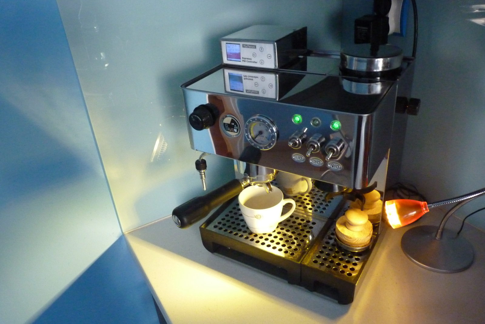
It is a design of PID controller for coffee maker (in this case it is La Pavoni Domus Bar, but the controller can support practically every coffee maker or any other heating/cooling unit with a power up to 1,5kW). The main reason for creating this device was significant hysteresis of factory controller (almost 10 degrees Celsius) and the consequent problems with the repeatability of percolate process.
Assumptions of the project:
- reducing interference in express to a minimum
- safety of use
- built-in heater control, without any external contactors and SSR
- the quick exhaust valve control – allowing “pre-infusion”
- pump enable time control, the possibility of profiling the pressure in the future
- built-in second hand for measuring time of extraction, RTC
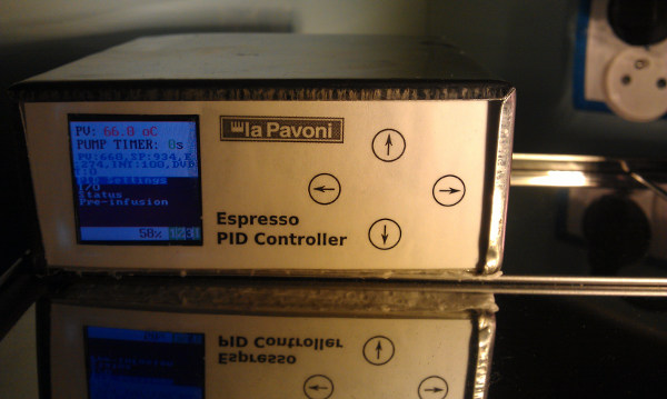
- visualization of settings and process parameters on the LCD
- changes of the settings from the menu, in real time
- style similar to the style of coffee maker
Hardware:
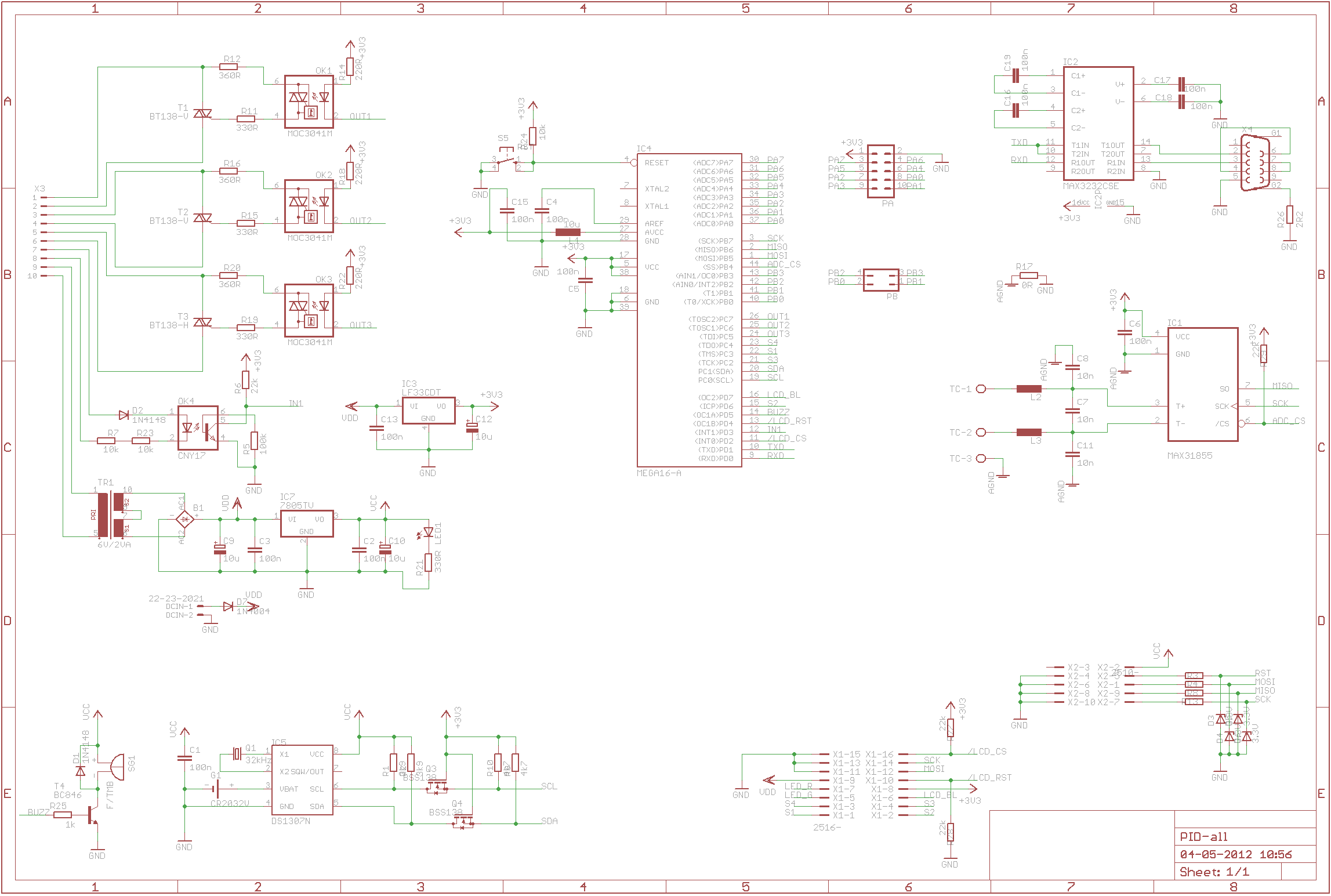
The controller has three optoisolated AC outputs with enabling in zero, including one high-current output for control over the heater and one optoisolated input 230V.
The measuring part of the device is based on MAX31855 and supports a K type thermocouple. Analog part with cool end compensation was integrated in the circuit with 14-bit ADC converter with SPI interface. Additionally the circuit detects interruption of the thermocouple circuit, grounding and short circuit to VCC, which proved to be quite problematic.
The main element of the circuit is microcontroller Atmega32A (although on the schematic it is Atmega16, but they differ in the amount of memory). The main criteria when choosing it were: built-in SPI and I2C, relatively big amount of Flash memory (fonts, graphics), powered from 3,3V, timers including one with PWM output.
The circuit is powered from transformer 6V, 2VA. 3,3V for chips is taken from LDO stabilizer, and LCD backlight is powered directly from behind the bridge, with additional possibility of PWM keying.
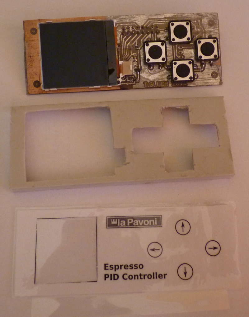
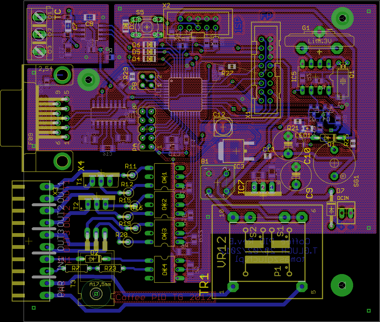
Schematic and PCB were made in Eagle, the double-sided boards were made in thermal transfer method. When you do not have a HotAir, it may be difficult to solder the socket of LCD. Panel board and high-voltage part were tinned with a paste for soldering copper pipes, heated with a burner, the rest was lacquered.
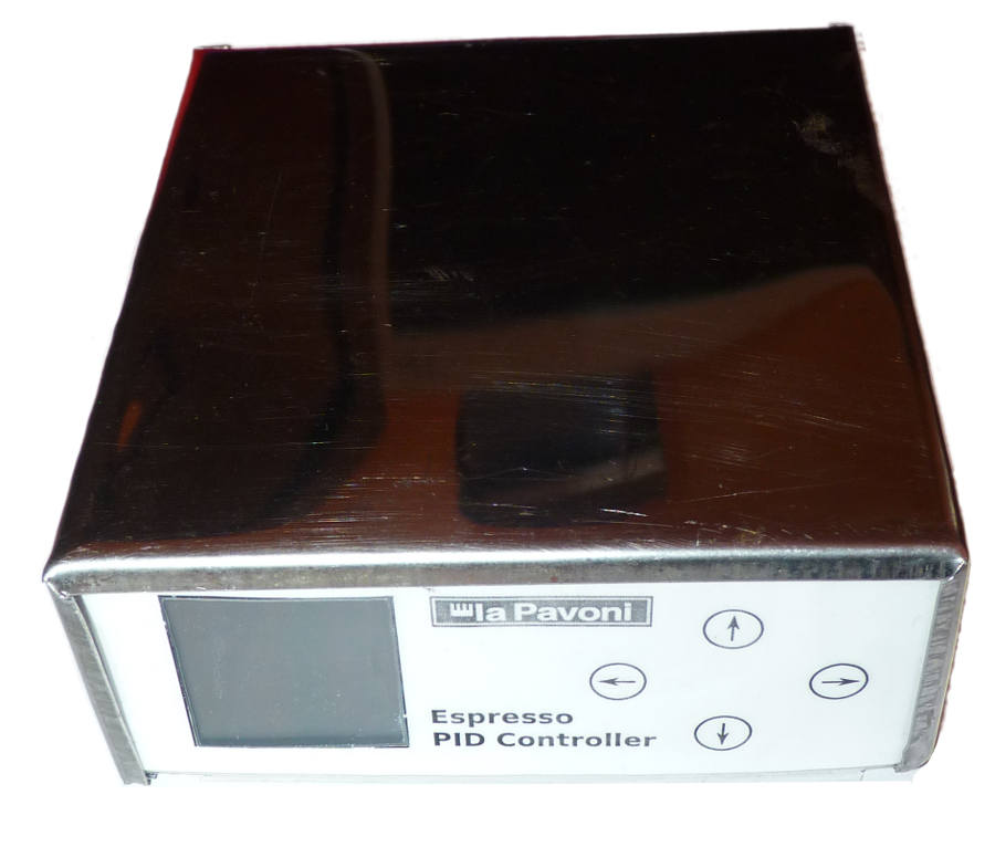
Housing was made of lacquered stainless steel plate, so that its style reminds the style of the coffee maker. It is connected with the safety cable/ housing of the coffee maker. All the cables (except TC) between the coffee maker and regulator are from an old cooktop, have a thick lagging and are resistant for high temperature.
Software:
Firmware was written in C (gcc + avr-libc), most of the code was written as non-blocking, although due to lack of “frame buffer”, refreshing the content of LCD takes a while. LCD based on driver PCF8833 was removed from Nokia 5100. Due to the fact that the frame has 9 bits, the first bit is sent in program, and the next 8 are sent from the built-in SPI. Processor operates on 7372800Hz, refreshing the whole screen would be time consuming, so when it is possible, updates are carried out in fragments. Parameters of the process (on the top) and I/O state (on the bottom) are refreshed every 1s.
Smooth operation is provided by dividing tasks of drawing and minimization of their occurring. Support of the display, I/O, filtration and PID occupies less than 1 system tick (about 10ms). Most of the Flash memory is occupied by fonts (8x8 and 8x16) and support of floating-point numbers from avr-libc.
All the settings can be changed from the menu, what is shown on the video. Due to the variables type, at the moment K and Ti are an integer, which results in the setting range, but is sufficient to set the stable regulator with satisfactory parameters.
Useful links:
**broken link removed**
Video
Pictures:

Link to original thread (useful attachment) - **broken link removed**