Continue to Site

Welcome to EDAboard.com

Welcome to our site! EDAboard.com is an international Electronics Discussion Forum focused on EDA software, circuits, schematics, books, theory, papers, asic, pld, 8051, DSP, Network, RF, Analog Design, PCB, Service Manuals... and a whole lot more! To participate you need to register. Registration is free. Click here to register now.

PIC RMS calculation C-code

Status
Not open for further replies.
The 1rst algorithm you posted, already provide a guideline to calculate, based on root-mean-square formula :

Code:
rawrms += adcbuf[count] * adcbuf[count] ;


+++
 

As I keep trying to explain, there is nothing magic about RMS values. The RMS, and peak are proportional to each other. RMS is difficult to measure, peak is easy. Measure the peak and calculate the RMS from it if you need to but even comparing peak voltages should be enough. If you want an RMS equivalent of a peak sine measurement, divide by sqrt(2), if its a modified sine or some other wave shape, divide by an apropriate amount. Look for more information atL https://masteringelectronicsdesign.com/how-to-derive-the-rms-value-of-pulse-and-square-waveforms/

I can't understand why a simulator should show ripple on an unloaded reservoir capacitor. 100nf should be enough, the only load on the rectifier will be the current through the potential divider and that should be very small. You CAN make the value bigger, it will not make the peak reading wrong but it does mean the response time to the voltage falling will be slower.

If you insist on taking many readings, you will need lots of memory, at least two bytes per sample if you are using a normal 10-bit ADC unless you use a rolling average calculation. It would probably be easier to use an RMS to DC converter, something like an AD536 or equivalent and measure it's DC output.

Brian.

I didn't use any RMS-to-DC IC before and I don't know if they are good or not.

someone suggested taking average rms readings... I'm still trying to do some code for it.

anyway... I came up with this kinda code to do it without average rms readings:


Code:
for (i=0 ; timer_interrupt == 1; i++) {

v_adc = (ADCRead(channel)*5)/1023;     // outputs 0-5 value
v_squared = v_adc*v_adc;               // square the 0-5v signal
               
Pacc = Pacc + v_squared;               // store the result in an accumelator
}

v_mean = Pacc/i;
v_rms = sqrt(v_mean);                    // takes the sqrt of the accumelated values
v = (v_rms *350)/5;                        // as 350v is the peak of actual voltage... I will rectify it and use a voltage divider... but no filter, so it can be like sinewave shape but +

^
this function returns v value... of course there's more stuff like variable types and so... And timer will count 20ms.

variable types:

Code:
unsigned int i;
float v_adc;
unsigned long v_squared;
double  v, v_rms, v_mean;
unsigned long Pacc;
unsigned short channel;

there are more variables... I am using PIC16F877A.

If the code is ok tell me so that if the MCU don't have enough memory I will consider changing it.

I insist on RMS calculation because some signals are square wave and saw-tooth... and some are distorted... so it's not pure sinewave always.

thx
 
Last edited:

RMS converter ICs are very good and accurate but they do add to the overall costs. They work regardless of the input wave shape.

Your code method is good but it might have some problems. The first is that you can't measure negative voltages with the ADC, the second is that 'i' increments repeatedly until the 20mS interrupt so there is a danger of it overflowing it's maximum value. A safer method would be to limit the measurement to a fixed number, say 200 samples at 100uS intervals. It may be easier to set the ADC conversion time to pace the measurements than to use timer interrupts. It really depends on how efficiently your compiler can handle floating point division and multiplication as these are usually slow to execute. If it seems too slow, try using the raw ADC readings without scaling to 5V each time.

Brian.

told u I rectified the signal so that the negative cycle now positive, but I didn't use any filters to keep it like sine wave but all positive cycles and this I think doesn't affect RMS.

about limiting readings and so.. I don't quite know how to do it really. You said correct stuff about overflow.

200 samples per 100 us? now you say this but I can't imagine how to do it, especially that taking ADC samples requires a subroutine that I made and this one I don't know how to calculate it's run time.

I use MikroC PRO for PIC. I will drop converting 0-1023 to 0-5 as it doesn't do any much good stuff.

___

I saw some ICs to convert RMS to DC but can you mention one that you used? and what's it's output?

should I feed it with the AC signal directly or reduce it a bit?

sorry for these much questions but I am still new and try to research everything you write.
 

People are using voltage dividers.

a voltage divider with AC? OK I can do it (I asked because I don't want to use a transformer).

so can I divide it to 5vp or 1vp?

If there is a good thread here, let me know.
 

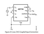
I tried the AD736 IC in Proteus ISIS and made a circuit according to the data sheet...

And it still give me 0v output... I had no luck with LTC1966 one as it still gives me 0v.

What do you think I need to do?

I will use a voltage divider to trim the 350vp to 5vp (or 1 as the IC requires) to feed the IC input. But this DC/AC coupling stuff I have a problem with.

thanks.

_________

photos:

datasheet circuit: dtsht.jpg

mine in proteus: proteus_sch.jpg
 

Yes, that's the problem with trusting Proteus. Just for fun, try to feed the input signal to VIN and ground CC, without any coupling capacitors. You'll notice that the simulation works, it's up to you to explain why. My suggestion would be a regular circuit simulator, e.g. LTSpice.
 

Yes, that's the problem with trusting Proteus. Just for fun, try to feed the input signal to VIN and ground CC, without any coupling capacitors. You'll notice that the simulation works, it's up to you to explain why. My suggestion would be a regular circuit simulator, e.g. LTSpice.

OK, I removed the input cap and it worked. But with a lot of ripple... it's not pure DC which is a problem.

I need Proteus because it's the only one that supports Microcontrollers like PIC.

my whole design is in it.

if I used my circuit or yours in real world as it's in the schematic, will it work?

also, how about LCT 1966 chip?
 

The simulation problems suggest that the Proteus AD736 model doesn't actually reproduce the chip's behavour.

Nevertheless I believe, that the simulated waveforms in standard circuit are correct. Ripple is present by nature of the rms circuit and will occur with other rms chips as well. The datasheet discusses the dimensioning of Cav and additional Cf for different applications.

A possible solution is to accept a certain amount of ripple and let a boxcar averager filter it in the microcontroller. The overall response time will be faster than ever achievable with purely analog signaöl processing.

I read your reply and modified it to be like this:

schem.jpg

and the generated waveform is like this:

scope.jpg

notice that the voltage source is 3vp AC 1Hz... but I noticed it gets better when increasing frequency...

I tried 5vp signal and 50Hz... it outputs 3.50v DC which is quite close to the 3.55 or so one.

after this, do you suggest that I buy the chip and use it regardless of the simulation?
 

1-3.

4. There's is no need for an exact sampling frequency. But the RMS measurement must be either performed on full periods, or use low-pass filtering sufficient to average the fluctuation caused by a different measurement window.

Hey FvM how are you ?
How do i do the low pass filtering (for not full periods), it must be done on the circuit like an RC filter or how??
Or in software but i don't know how because if i average all the samples i lose the "instantaneous" waveform...
Thanks in advance
 

By nature, an RMS measurement doesn't give instantaneous values.

Firstly you should clarify the purpose of your measurement. If it's intended to evaluate short-time magnitude variations, what are the prerequisites? Do you expect a sine waveform? If not, do you assume the shape to be maintained during magnitude variations? How much measurement value ripple is acceptable?
 

Thanks for your reply.
I want to do true rms calculation with a microcontroller without knowing the frequency of a non sinusoidal signal, so my measurement window won't be full periods.

I will calculate it with
N
Vrms = sqrt (sum (v*v)/N)
i=1
but the rms is not accurate so i have to do the low pass filtering that you stated but how do i do it?:smile: Because I have discrete values...
Thanks
 

Time discrete low-passes are rather simple, particularly a first order filter:

\[{y}_{n} = a{x}_{n}+(1-a){y}_{n-1 }\]

For smaller a values, the filter time constant is about 1/(fs*a).

But as already discussed, there's a settling time versus ripple trade-off if you don't average full cycles. I think you should calculate the expectable performance before you start the design. If the RMS measurement is applied to periodical waveforms, it may be easier to indentify the cycle time.
 
Status
Not open for further replies.

Similar threads

Part and Inventory Search

Welcome to EDABoard.com

Sponsor

Back
Top