Continue to Site

Welcome to EDAboard.com

Welcome to our site! EDAboard.com is an international Electronics Discussion Forum focused on EDA software, circuits, schematics, books, theory, papers, asic, pld, 8051, DSP, Network, RF, Analog Design, PCB, Service Manuals... and a whole lot more! To participate you need to register. Registration is free. Click here to register now.

PIC 18F4550 ADC with UART and wireless

Status
Not open for further replies.

neo_one

Junior Member level 2
Joined
Oct 26, 2011
Messages
22
Helped
0
Reputation
0
Reaction score
0
Trophy points
1,281
Activity points
1,445
Hi,

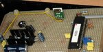
I am using PIC 18F4550 with internal RC oscillator to transmit data serially to a 433 Mhz wireless ASK module. Since the typical baud rate of the transmitter is 1kbps(from datasheet), I have set SPBRG as '12' which is around 1200bps for 1 Mhz processor frequency (I think that is right as I am using internal RC oscillator). On the receiver side I am using another 18F4550 with same SPBRG '12' setting. The received data in RCREG is to be given to port D.

As of now, the data is sent and received correctly, but I cannot get the result in the port D.

Can anyone help me?
 

Thank you wp100, I'll try giving a pause in between. Actually I simulated the circuit in proteus and it worked fine. Can you please tell me if anything is wrong in the code?
Code:
Start:

	CLRF WREG
	CLRF RCSTA
	CLRF PORTD
	CLRF TRISD
	CLRF PORTA
	CLRF TRISA
	CLRF PORTB
	CLRF TRISB
	CLRF RCREG
	CLRF TENS
	CLRF ONES
;**************************************************************************
;Receiver Program begins
RECEIVE:
; ASYNCHRONOUS RECEIVER CONFIGURATION
	;Baud rate setting UART
		MOVLW D'51' ; 1200bps
		MOVWF SPBRG
		;BSF BAUDCON, RXDTP ; Received signal inverted
		MOVLW B'10000000' 
		MOVWF RCSTA ; Serial port enabled
		BSF RCSTA, CREN ; Continuous receive enable (Asynchronous)			
back:
		
LABEL:	BTFSS PIR1, RCIF ; Receive flag status check for receive complete
		GOTO LABEL

        	MOVFF RCREG, PORTD
 

Hi,

If you see that tutorial it does not use the USART serial link.

This tutorial is about using licence free radio modules, most countries now have such modules available at low cost, although the exact frequencies may vary between different countries. If you've tried to send plain RS232 via these modules, you've probably found that it doesn't work?
 

I am not using RS 232. I am using an ASK module and UART. The typical baud rate of it is 1kbps. That is why I tried to send at 1200 bps. Will it not work?
 

I am not using RS 232. I am using an ASK module and UART. The typical baud rate of it is 1kbps. That is why I tried to send at 1200 bps. Will it not work?

Hi,

Its just his use of the word RS232, he actually means Serial via the USART.

There are many threads in this forum about these =RF modules.

This one should convince you https://www.edaboard.com/threads/237573/
 

Hi,
Still no luck with the wireless transmission. Are you sure that without manchester encoding it will not work? Can you suggest any link for manchester coding and decoding in assembly?
 

Hi,
Still no luck with the wireless transmission. Are you sure that without manchester encoding it will not work? Can you suggest any link for manchester coding and decoding in assembly?


Hi,

Well that WinPicProg tutorial worked for me when I converted it to run on a 18F4520.
Pic of transmitter below.

Why not post your full Send and Recieve routines nd circuit diagram, perhaps we can see where its going wrong.

If all else fails I can perhaps find a copy of my code.
 

Attachments

  • 2009-12-27 005.jpg
    2009-12-27 005.jpg
    67.8 KB · Views: 99

Why not post your full Send and Recieve routines nd circuit diagram, perhaps we can see where its going wrong.

This is my code

Transmitter
Code:
; internal RC osc and 300 baud

    LIST P=18F4550, F=INHX32        ; directive to define processor
    #include <P18F4550.INC>         ; processor specific variable definitions

;**************************************************************************

;   Oscillator Selection:
    
    CONFIG WDT=OFF                  ; disable watchdog timer
    CONFIG MCLRE = ON               ; MCLEAR Pin on
    CONFIG LVP = OFF                ; disable low voltage programming
    CONFIG FOSC = INTOSCIO_EC       ; internal oscillator
    CONFIG PBADEN = OFF             ; PORTB all digital

;**************************************************************************

; Reset vector
; This code will start executing when a reset occurs.
	RESET_VECTOR CODE 0x0000
    goto	Start		            ; go to start of main code

;**************************************************************************

; Start of main program

Start:
; Initial clearing of all registers involved
    CLRF   WREG
    CLRF   PORTD
    CLRF   TRISD
    CLRF   PORTB
    CLRF   TRISB    	
    CLRF   TXSTA
		
    ; BAUD RATE GENERATION	
    MOVLW  D'12'
    MOVWF  SPBRG	
    
    ; ENABLING SERIAL PORT
    MOVLW  B'10000000'
    MOVWF  RCSTA

    ; ASYNCHRONOUS TRANSMIT MODE SELECTION
    MOVLW  B'00100000'
    MOVWF  TXSTA
	
    ; ADC programming begins here.

    ; VSS,VDD ref. AN0 analog only
    MOVLW  B'00001110'
    MOVWF  ADCON1

    ; clear ADCON0 to select channel 0 (AN0)
    CLRF   ADCON0 

	
    ; ADCON2 setup: Left justified, Tacq=2Tad, Tad=1/FRC (Internal RC Oscillator)
    MOVLW  B'10001011'
    MOVWF  ADCON2
	
    ; Enable A/D Conversion Module
    BSF    ADCON0,ADON 

MainLoop:
    CLRF   ADRESH
    CLRF   ADRESL
    BSF    ADCON0,GO_DONE       ; Start A/D Conversion
adc:
    BTFSC  ADCON0,GO_DONE       ; Loop here until A/D conversion completes
    GOTO   adc
    
    MOVFF  ADRESH, PORTB        ; ADC result high register transferred to Port D
    MOVFF  ADRESL, PORTD        ; ADC result low register transferred to Port B

Transmission:

    MOVF   ADRESL, W            ; get low byte of analogue value
    CALL   TRANSMIT             ; send unformatted to serial    
    CALL DELAY
    GOTO   MainLoop             ; Sampling of next value initiated

TRANSMIT:	
			
LABEL:	
    BTFSS  PIR1, TXIF           ; wait for transmit buffer empty
    GOTO   LABEL
    MOVWF  TXREG                ; send the byte in W reg
    RETURN

DELAY:
	MOVLW 0Xff
	DCFSNZ WREG
	GOTO DELAY
	RETURN
	
    END

The receiver program

Code:
LIST P=18F4550, F=INHX32	;directive to define processor
#include <P18F4550.INC>	;processor specific variable definitions

;**************************************************************************

;   Oscillator Selection:


		CONFIG WDT=OFF; disable watchdog timer
		CONFIG MCLRE = ON; MCLEAR Pin on
		CONFIG DEBUG = ON; Enable Debug Mode
		CONFIG LVP = OFF; 
		CONFIG FOSC = INTOSCIO_EC


;**************************************************************************

;Reset vector
; This code will start executing when a reset occurs.

RESET_VECTOR CODE 0x0000

;		goto	Main		;go to start of main code

;ORIGIN OF THE PROGRAM
ORG 0
;		goto	Main		;go to start of main code

;**************************************************************************

;Start of main program

Start:

	CLRF WREG
	CLRF RCSTA
	CLRF PORTD
	CLRF TRISD
	CLRF PORTA
	CLRF TRISA
	CLRF PORTB
	CLRF TRISB
	CLRF RCREG
	CLRF TENS
	CLRF ONES
;**************************************************************************
;Receiver Program begins
RECEIVE:
; ASYNCHRONOUS RECEIVER CONFIGURATION
	;Baud rate setting UART
		MOVLW D'12' ; 1200bps
		MOVWF SPBRG
		;BSF BAUDCON, RXDTP ; Received signal inverted
		MOVLW B'10000000' 
		MOVWF RCSTA ; Serial port enabled
		BSF RCSTA, CREN ; Continuous receive enable (Asynchronous)			
back:
		
LABEL:	BTFSS PIR1, RCIF ; Receive flag status check for receive complete
		GOTO LABEL

        	MOVFF RCREG, PORTD


END

The result in RCREG has to be out in port D
 

Hi,

Have looked at the code you have sent, but that is just a simple Usart routine, and rather incomplete.

My best suggestions would be for you to get yourself some much simpler 16F chips than the complex 4550.

Then go though a tutorial like the WinPicProg I linked earlier.

You might be much better going though most of the course so you build up your skills.
At least do the simple USART /RS232 routines first then you can move on to the RF/ Manchester coding routines for the 433mhz units.
( for his adc tutorial the buffer amp is not needed for simple inputs)

Can those RF unit just operate on simple serial ? no. I have scoped the output from the Receiver when the transmitter is powered off and its full of signals from all over the place, so its essential some form of encoding is used otherwise your data just gets lost in all the other spurious signals.
 

Status
Not open for further replies.

Similar threads

Part and Inventory Search

Welcome to EDABoard.com

Sponsor

Back
Top