Continue to Site

Welcome to EDAboard.com

Welcome to our site! EDAboard.com is an international Electronics Discussion Forum focused on EDA software, circuits, schematics, books, theory, papers, asic, pld, 8051, DSP, Network, RF, Analog Design, PCB, Service Manuals... and a whole lot more! To participate you need to register. Registration is free. Click here to register now.

phse control light dimmer

Status
Not open for further replies.

bonhome

Newbie level 4
Joined
Mar 4, 2011
Messages
5
Helped
2
Reputation
4
Reaction score
2
Trophy points
1,283
Activity points
1,332
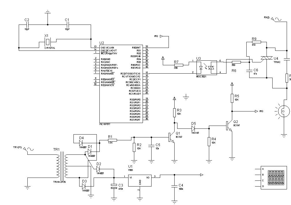
hello i h've been working on a phase control light dimmer project with pic 16f877 microcontroller with ccs pic c compiler driving a MOC3021 optotriac
controling a lamp 220 v 50 hz .i can say that i know the principle well ,so i wrote this c code,and for some reason it does not work.
well in this case i am trying to control the lamp at 3 defrents phases 100,75,50 %
int porcentage=100;
#int_EXT
EXT_isr()
{
if(porcentage==50)
{
delay_us(4990);
output_high(PIN_C0);
delay_us(100);
output_low(PIN_C0);
// set_timer1(5000);

}
else if(porcentage==75)
{
delay_us(2480);
output_high(PIN_C0);
delay_us(100);
output_low(PIN_C0);
// set_timer1(2500);
}
else if(porcentage==100)
{
output_high(PIN_C0);
delay_us(100);
output_low(PIN_C0);

}


}


void main()
{

port_b_pullups(FALSE);
setup_adc_ports(NO_ANALOGS);
setup_adc(ADC_OFF);
setup_psp(PSP_DISABLED);
setup_spi(FALSE);
setup_timer_0(RTCC_INTERNAL|RTCC_DIV_1);
setup_timer_2(T2_DISABLED,0,1);
enable_interrupts(INT_EXT);
ext_int_edge( H_TO_L );
enable_interrupts(GLOBAL);
set_tris_c(0b11111110);

while(1){

}

}
so if anyone could help me i would apretiate it. thank you.
 

I assume you are working from a zero cros point and controlling a triac! Is this correct? When you say it doesn't work what do you mean exactly/ What happens?

dfullmer
 

Your logic seems to be correct.

Post your full schematic, there may be some error in zero crossing.
 

hi

when you control the phase, you have to detect the zero crossing at both the sides and apply the triggering sequence

ml
 

the zero cross crcuit is working fine,it does trigger an externel interrupt ,wich execute an ISR.i am using isis proteus simulator an for some reason i have a timing probleme and it is crashing .
 
the zero cross crcuit is working fine,it does trigger an externel interrupt ,wich execute an ISR.i am using isis proteus simulator an for some reason i have a timing probleme and it is crashing .

simulator crashes??
may be software problem.

Tell me what is happening clearly..
 

Hi everybody

If we need to control at different phases we need to use non-zero cross TRIAC Driver example MOC3011. Now detect the zero cross using voltage drop and opto-couple accross the Live or Hot wire. Remember here not to connect reverse. That's all rest is done by software, we can control a very smooth almost linear control.

Thankyou

PS: Try to change to MOC3011 and see. I think you are trying to sense through half wave rectifier. I suggest direct sense would give you better results. Connect a IN4007 and then 33K on the live or Hot wire and connect to an Opto-coupler like 4N35, now sense the output of optocoupler.
 
Last edited:

in the 50 % case i need to wait 5ms to trigger the TRIAC ,with the osciloscope it shows that is longer then the entire sicle of the input .allthough i ma using i 50hz input ,onse a zeros cross interrupt the microcontroller a 5ms delay seems to hang the ISR longer than the time it takes for the next interruption.

---------- Post added at 14:47 ---------- Previous post was at 14:45 ----------

using a 50hz frequency should have 20ms sicle and 2 times interruption after each 10ms ,the problem that my code is for some reason concedering a 5ms delay longer than the 10ms of half sicle.

---------- Post added at 14:52 ---------- Previous post was at 14:47 ----------

thanks for your post prmurthy ,but the zeros cros sence is working fine,and i am using a non eros cross TRIAC driver MOC3021
 
I am trying to design a very simular circuit, only using circuitry and no pic.. Since I am having problems I am considering using the sam pic. I tryed to stay away from programming, I find its not my strong point!!:-|
Does the trigger have to be an interrupt?? Im looking to vary the phase output buy varying a voltage input to the pic from 0-5 volts. Its an analog signal so would i have to use an A/D converter. Is this possible??
Thanks
 

Hi,

Take a look at this light dimmer (mikroc) project :
 
Last edited by a moderator:

Dear bonhome,
Did u get the succes in phase control AC dimmer.. Please send reply I'm also stuck here.
Thanking You.
Praful
 

Status
Not open for further replies.

Part and Inventory Search

Welcome to EDABoard.com

Sponsor

Back
Top