Continue to Site
Follow along with the video below to see how to install our site as a web app on your home screen.
Note: This feature may not be available in some browsers.
Hi Dana,If you have a inverting amp then at DC, 0 Hz, the phase of the output
is inverted, 180 degrees.
If you have a non-inverting amp then at DC, 0 Hz, the phase of the output
is not inverted, 0 degrees.
Regards, Dana.
1) Do you mean that in inverting AMP the Y-axis will start at 180 for phase margin, and 0 for non-inverting?
What if the Y-axis started with more than 180? as in the previous figure?
") It was personal choice by author.
It was personal choice by author.Thank you Dana for the explantation,Yes on ques 1 above.
They started > 180 so they could show the 180 actual, so curve did not fall on axis and confuse
people. But we are confused
You measure phase margin and that is at unity G what is phase, and total from in to out
must be < 360 degrees. The ref point used is arbitrary, the < 360 is not arbitrary. Arbitrary
because you can graph including the internal DC phase shift or implied you already know
in your head what DC phase shift is.
Keep in mind internal phase is a f(freq) and is typically 1 or 2 pole, up to 90 or up to 180
due to the poles alone. Then we have the DC static phase to consider as well. 1 pole typical in
low speed op amps 2 or more in high speed.
Regards, Dana.
Hi LvW,The phase margin is defined based on the loop gain.
Normally, we only have negative feedback - and we open the loop at a suitable node to measure/simulate or calculate the loop gain.
That means: The negative sign within the loop (because of negative feedback) is and must be part of the loop.
For this reason, the phase function of the loop gain (defined as mentioned above) must ALWAYS start at -180 deg.
Therefore, prior to such a measurement you have to ensure yourself if the phase inversion (for negative feedback) is included in the analysis.
I strongly recommend to use only the above definition (including phase inversion) because there are many applications where this phase inversion does not take place at the summing junction of the loop (inverting opamp terminal) but somewhere in the loop. If this sign inversion is not taken into account for loop gain analysis, this can lead to some confusion (see your question).
No . this sounds not clear to me.Hi LvW,
Thank you for the reply,
So, the rule of thumb is: if the negative sign in the loop is taken, then the rule is (180+ phase at gain 0dB), right?
No . this sounds not clear to me.
The phase of the loop gain must start at -180 deg for negative feedback (when the phase inversion within the loop is taken into account). Thats all.
For finding the phase margin, you have to identify the phase ot 0 dB loop gain.
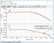
Whe the phase is 25 deg less than -360 deg - the PM is 25 deg.
In this case, the other form of the criterion applies, of course.Could you see the previous picture? there is no -360 in the first figure for example, so how can I know the value of PM? ( in case the negative is not taken in the loop)1
Thank you LvWIn this case, the other form of the criterion applies, of course.
When the phase inversion for neg. feedback is not considered, the stability limit is, of course, at another -180deg phase shift (and with consideration of the inversion it is at 0 deg resp. at -360 deg).
Does this not sound logical?
By the way: Here is another argument in favour for the 360deg-criterion: Only in this case, the loop gain determination is in accordance with the oscillation criterion formulated by H. Barkhausen (unity loop gain with zero resp. 360 deg phase shift)