Continue to Site

Welcome to EDAboard.com

Welcome to our site! EDAboard.com is an international Electronics Discussion Forum focused on EDA software, circuits, schematics, books, theory, papers, asic, pld, 8051, DSP, Network, RF, Analog Design, PCB, Service Manuals... and a whole lot more! To participate you need to register. Registration is free. Click here to register now.

Output Voltage of Diode Bridge Rectifier vs. RLoad

Status
Not open for further replies.

Politecnico

Member level 1
Joined
Aug 28, 2013
Messages
34
Helped
1
Reputation
2
Reaction score
1
Trophy points
8
Activity points
316
Dear All

Hi,
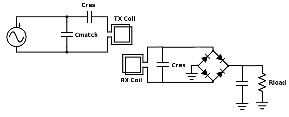
I have a wireless power transfer circuit as follows:


Now, I can measure the DC rectified voltage equal to 5.5V, 3.5V, 1.5V and 0.5V for Loads equal to open, 100K, 10K and 1K, respectively. However, I don't understand why the rectified voltage decreases while the value of RLoad decreases? Any idea to improve the stability of Vout vs. RLoad?

Thanks a lot,
 

Hi,

Where do you measure the voltage? The smaller the resistor, the higher the current, the lower the voltage.
 

It's normal.Even you have successfully transfer the power obtained from the source with a proper impedance matching, the coils will act as a transformer and secondary side internal resistance ( and diode intrinsic impedances) will limit the power to be transferred to the load.It's called as " available power" and it's also well known in electrical ( any ) circuits.
In order to improve the power to be transferred to the load resistance, you should decrease internal RF impedances of the coils,decrease the diode intrinsic impedances etc.
That's like improving available power from the source problem.
 
Status
Not open for further replies.

Similar threads

Part and Inventory Search

Welcome to EDABoard.com

Sponsor

Back
Top