Continue to Site

Welcome to EDAboard.com

Welcome to our site! EDAboard.com is an international Electronics Discussion Forum focused on EDA software, circuits, schematics, books, theory, papers, asic, pld, 8051, DSP, Network, RF, Analog Design, PCB, Service Manuals... and a whole lot more! To participate you need to register. Registration is free. Click here to register now.

Oscilloscope circuitry - help needed

Status
Not open for further replies.

cipi-cips

Member level 4
Joined
Jun 30, 2008
Messages
76
Helped
2
Reputation
4
Reaction score
1
Trophy points
1,288
Activity points
1,867
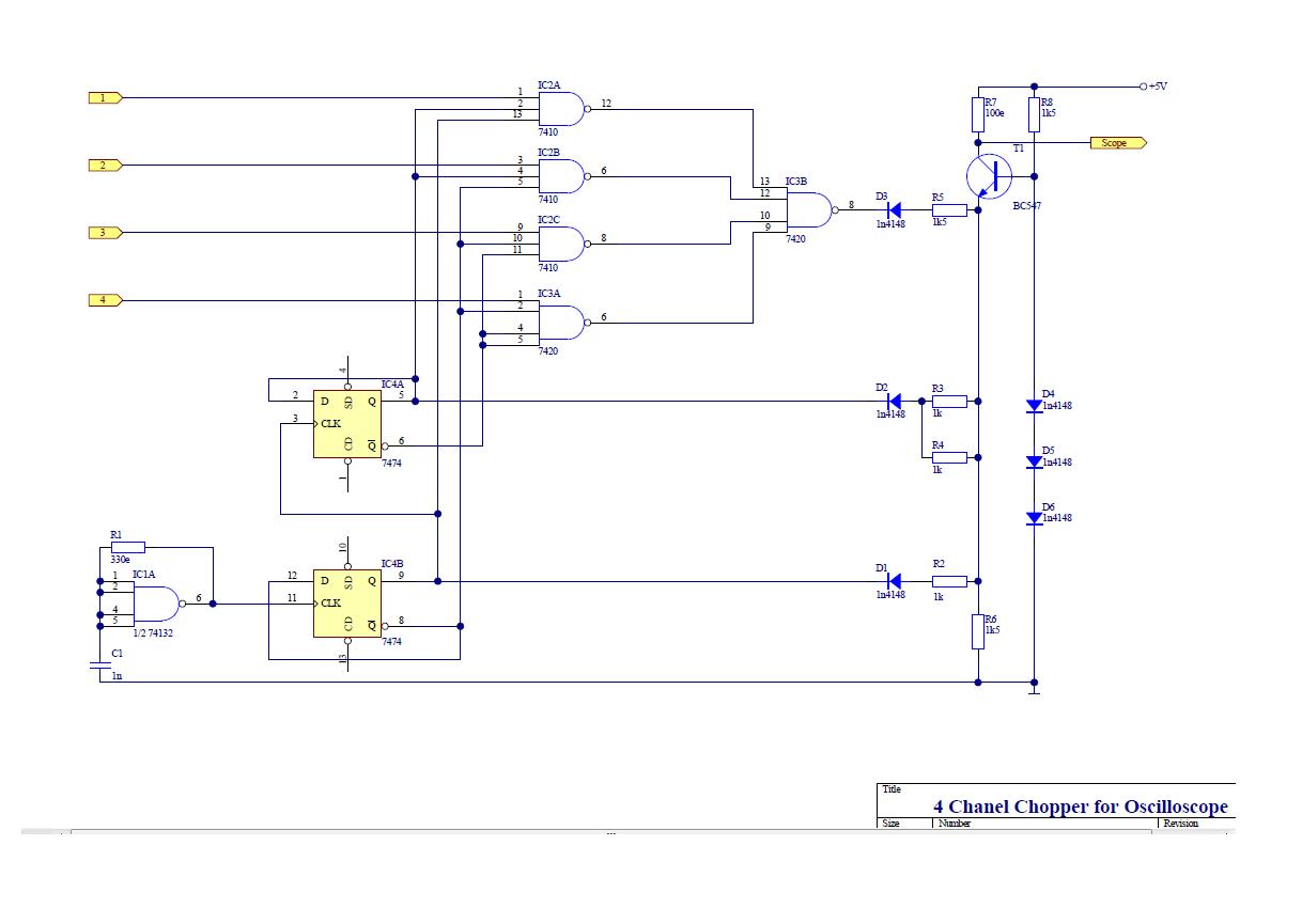
schematic for oscilloscope to show 4 signals

Hello I manage to find this circuit so if someone can tell me does this work, this is the circuit for analog oscilloscopes, and point of this circuit is showing 4 digital signals on one oscilloscope CH ?


shematic for osciloscope to show 4 signals


Enjoy :)
 

oscilloscope connections

I have build this circuit in EWB, and when I look at oscilloscope I dont get 4 signals that I have brought on inputs, I get something what look likes lots of distortion ?
 

check oscilloscope offset

This is a too complicated chopper for a logic analyzer, however seems OK, except maybe the output DC level converter. The output "fixed current source" is a variable current source driven by the logic signals.
 

oscilloscope multiplexer circuit

Hello guys I have build this circuit and I have tested it on oscilloscope and I have some problems :(

Well when I connect output to oscilloscope instead of 4 signals I get only two signals ch1 and ch2 but the rest ch3 and ch4 are not on display of oscilloscope,

First I thought that there is a problem with circuit board but I've checked it 10 times and there are no wrong connections, so could you possibly know what seams to be the problem or some hint to tell me :) ???
 

oscilloscope, input multiplexer

Well I think there is no point for continuing this circuit because I always get same results so I think that I need some new circuit..

Lots of ppl says that there are many of this schematic's for oscilloscope but I cant find them I've only find 2 of them and I have build one but it isn't working second one is this
http://www.piclist.com/images/www/hobby_elec/e_oscillo.htm

and problem with this is that this is to complicated I need some simple schematic because I need to analyze 4 digital signal's... Well if someone of you know or has build some circuit like this can post it here


btw this is my graduating work so I need to build it so I can finish my school!!!
if you can help somehow I will be glad-full very much !![/url]
 

russian analog oscilloscope

does anyone know what is the name of that circuit that can show many signals on one channel of oscilloscope I try to google it but I dont know what is the name of that
 

Re: Oscilloscope

I think that could be the problem I will make pcb again with that connection and I will see does it works

thx for helping

Added after 3 minutes:

Could be the problem in IC4A pin 12 and 9 are misswired, maybe pin 12 should be connected with pin 9 instead of pin 8?
 

Re: Oscilloscope

Sorry, I don't have time to go thru it in depth right now. Get the clock part working like a divide by 4 counter, and we can take it from there.
 

Re: Oscilloscope

I'll change the connections of pins and I will report how does it work
 

Re: Oscilloscope

If you get the counter to count, then if it is still not working, you want to check the logic in the four nand gates. You have the Q and notQ counter outputs, you need to draw up a truth table and see how the four inputs get multiplexed, one at a time to the output.

You also have to make sure that the level shifting diodes are working properly to give you four different DC level shifts as the nand gates are activated.
 

Re: Oscilloscope

thx working on counter :)
 

Re: Oscilloscope

Ok I have created a circuit that connects pin 2 with 6 and I get very very bad results, at the output I get only 1 signal :(
 

Re: Oscilloscope

how do you mean if I get counter to count because I can simply create divider by 4 with D Flip Flop

URL]


If you look at schematic you can see that only pin 2 is miss connected but when i connect it like divider by 4 results are crappy I dont get nothing accept one signal at the output instead of four :( kinda lost here ???
 

Re: Oscilloscope

The design steps are:
1) get the counter to work. You want a 2-bit output. The 2-bit output has four counting states: 00, 01, 10, 11. Sounds like you have this already if you use the D flip flop.
2) Use a diode and a series resistor R, to connecto to Qa output. This is you MSB current offset. Use a second diode ans a series resistor R, to connect to Qb output. This is your MSB current offset (1/2 the size of the first one). Sum those two offsets, plus your input signal, to give the (input + offset)--in 4 different offset flavors.
3) Use some sort of multiplexing circuit using QA, notQa, Qb, notQb to select one of the four input signals as a function of the 2-bit count input. You have to grind thru the logic to make sure the inputs are selected one-at-a-time.

THen you are done.
 

Re: Oscilloscope

I have made this and this is how the counter works, now I have 4 different signals at output Qa, Qa(not), Qb and Qb(not), like shown on picture

So what do you think about that? and if is it good now I must create logic for multiplexing and I must use that 4 different signals ?

[URL=https://img200.imageshack.us/i/sdasdsao.jpg/]**broken link removed**[/url]
 

Re: Oscilloscope

Good. What you are trying to do is a system design. Your system has 3 blocks to it:
1) clock
2) input multiplexer
3) voltage offset summing junction

You have designed and tested the 1) clock portion.
 

Re: Oscilloscope

Now you want to work on 2) input multiplexer. Here is ONE way to do it, with AND gates (for simplicity in understanding). When the other two inputs are "1", then the AND gate will let the third input signal pass through. By using Q0, Q1, notQ0, notQ1, you can set up the four AND gates to only pass one of the four inputs at a time. (note, if you want you can just buy a digital multiplexer chip to replace all of this, like a 74HC153, etc).
 

Re: Oscilloscope

And finally, you need to offset the four inputs with four different voltage offsets, one-at-a-time. You use the four states of Q1, Q0 to do this by summing in four different currents through two diodes at a transistor emitter. Caution, you should double check this part, as I did not go thru it in detail to make sure it is working as it should (I just copied the original schematic and clarified).
 

Status
Not open for further replies.

Similar threads

Part and Inventory Search

Welcome to EDABoard.com

Sponsor

Back
Top