Continue to Site

Welcome to EDAboard.com

Welcome to our site! EDAboard.com is an international Electronics Discussion Forum focused on EDA software, circuits, schematics, books, theory, papers, asic, pld, 8051, DSP, Network, RF, Analog Design, PCB, Service Manuals... and a whole lot more! To participate you need to register. Registration is free. Click here to register now.

Optocoupler to SCR gate interfacing

Status
Not open for further replies.

JonathanRalph

Newbie level 6
Joined
Aug 27, 2016
Messages
14
Helped
0
Reputation
0
Reaction score
0
Trophy points
1
Activity points
131
Good day

I would like to isolate the control side of the circuit from the power side by using an optocoupler. As shown in the picture below, I connected the anode of the scr to the collector of the optocoupler bjt and then connected the emitter to the gate (with a resistor and a schottky diode in between). But I'm worried that the optocoupler may not withstand 220Vrms. I looked at the 4N25 datasheet and found that the collector-emitter breakdown voltage of the optocoupler bjt is only 70V.

From the schematic, is there a proper way of interfacing the optocoupler to the SCR circuit to trigger the SCR properly without damaging the opto?

Specs:
Bridge rectifer: 1000V 35A
SCR: 600V 30A
Control side of the circuit is not shown for simplicity. It is assumed to be correct and working.
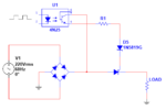
aaa.png
 

Hi,

there are dedicated opto-triacs for this.

From Fairchild they are named MOCxxxx. Like MOC3052M.
(there are other manufacturers like: Vishay, Isocom, Toshiba, Sharp...)

Read related documents, datasheets and application notes from any manufacturer to find the perfect optocoupler for your application.

Klaus
 

Is there a way to reduce the voltage going to the optocoupler's bjt? I only have the 4N25 opto and I may not acquire a more suitable optocoupler here. But I won't force it if there aren't any good suggestions.
 

Hi,

I don´t think there is a way to reduce voltage.

Expect 1.414 x RMS_input_voltage positive. = 311Vp
The negative voltage is floating. This is not a good situation. I recommend to suppress voltage with the use of a resistor and a diode in series.


Klaus

- - - Updated - - -

Added:

Keep in mind that with your circuit.. and a (slightely) inductive load the SCR might fail to open.


Klaus
 
Assuming that I have the right optocoupler, correct phase triggering, and additional smoothing capacitors in parallel with the load (the load is a DC motor by the way). Is the circuit feasible?
 

Hi,

I have my doubts.

With the motor as inductive load there is DC current through the SCR. Even when the input voltage has a zero cross, that does not mean the the current through the SCR becomes zero.

***
Use a triac (and a MOC) in front of the bridge rectifier and the problem is not existent anymore. The current will become zero...even it is delayed to the voltage.
The triggering is the same as with your circuit.


Klaus
 
You don't want "smoothing capacitors" parallel to the load because they cause high peak currents that possibly damage the SCR.

An important parameter is the SCR trigger current. Besides the already discussed voltage rating problem, it's unlikely that a BJT optocoupler can source the required trigger current. In so far the design is not feasible.

Usually a SCR is triggered by a trigger transformer, or a low voltage source tied to the cathode potential.
 
A DC motor rquires a chopper (buck) ckt for proper control... a triac in front of the bridge rectifier will work to a limited extent, if you just want on/off then a relay...
 

Status
Not open for further replies.

Similar threads

Part and Inventory Search

Welcome to EDABoard.com

Sponsor

Back
Top