Continue to Site

Welcome to EDAboard.com

Welcome to our site! EDAboard.com is an international Electronics Discussion Forum focused on EDA software, circuits, schematics, books, theory, papers, asic, pld, 8051, DSP, Network, RF, Analog Design, PCB, Service Manuals... and a whole lot more! To participate you need to register. Registration is free. Click here to register now.

opamp osciltions problem which didnt show on LTSPICE

yefj

Advanced Member level 4
Joined
Sep 12, 2019
Messages
1,237
Helped
1
Reputation
2
Reaction score
3
Trophy points
38
Activity points
7,444
Hello , i have designed with a big help from this forum a driver.
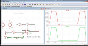
at first glanse it amplified great the signal how ever when i probed R1 resistor as shown below on my lab scope with DC input , i saw oscilations.
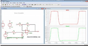
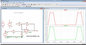
Now when i did step responce of the circuilt as shown below i see the oscilations.
I also know from analog design course that i can try and see the AC responce.
LT1028 is -1 stable ,how does it influence the connection between the stages so i will not get oscilations.
What could cause instability in such configuration?
Thanks.

1704747020456.png


1704745962928.png

1704746912539.png


1704746711098.png
 
Hello Klaus ,I am Tuning a YIG FM coil with this device.
The frequency range of the YIG is about 12MHz at 9.5Ghz certer frequency.
Tony said that i was wrong when thinking that my analog driver needs 0 bandwidth( DC input only)
I dont understand how the BW of the driver has anything to do with the YIG FM coil?

The FM coil data:
sesitivity: 450 KHz/mA
3dB bandwidth 2.2MHz
resistance 2Ohm
inductance 1.5uH

How this data influnces of the requirements i need to implement on the driver?
Thanks.

Hi,

Thanks Dana again for the simulation.

The datasheet says LT1028 is stable with inverting circuit and A = -1.
So your inverting setups show ringing. Quite expectable.

But I was surprised by your first non inverting setup showing very stable condition on A = +1, while the datasheet says it is not stable.

Now the second setup with feedback resistor meets more my expectations. Lots of ringing, at the edge to oscillate.

Thanks again.

On the other hand the LT1028 is a very low noise OPAMP. It has an input noise less than a 50 Ohms resistor. So noise wise it makes no sense to use input impedances higher than those 50 Ohms.
An often with that low noise ... one needs an amplifier with high gain. So with high gain and low input impedance the LT1028 works great. I uset it this way in some high end audio circuits decades ago.

*******

So the conclusion to this thread is, that the LT1028 is not the best choice for this application. The application does not need that extremely low noise but it needs stability. I still vote for local feedback combined with the use of a unity gain stable OPAMP. But indeed I still don´t understand what the OP really wants to achive. The requirements regarding timing, the freqency range ... the true goals.

Klaus
 
I'll let Klaus respond to the above.

Meanwhile, it's been so long since I have read the LT1028 datasheet, it turns out it can drive the reduced spec of 20 mA and more. But how does this amplify DBM compensated error frequency to pull the YIG to lock on to the reference signal with low phase noise but initial huge frequency error?
Answer : It doesn't.

There needs to be a way to coarse tune, then fine sweep and tune the error signal to compress massive frequency error then search and lock onto it. There needs to be specifications for FM gain, phase gain and thus phase noise in dB uA. @yefj needs to understand what the system needs to work with a hundred specs, then define the expected error disturbances like YIG hysteresis microphonics, driver resonance, supply noise, cable crosstalk, masssive frequency gain MHz/uA ( or GHz/mA) and define a better spec before asking for advice on how to achieve the unknown.
--- Updated ---

What are the real RLC specs for the YIG?

The FM coil data:
sesitivity: 450 KHz/mA
3dB bandwidth 2.2MHz
resistance 2Ohm
inductance 1.5uH

Or the previous RLC parameters? What about hysteresis, phase noise and microphonics and RF power level?

Meanwhile, @yefj needs to get serious about detailed goals and realistic specs. He is trying to duplicate the high power injected extreme low phase noise of a YIG Oscillator from an IEEE Member and Sr. Eng at NIST who has similar experiences I had in the late 70's on Time and Frequency and much RF exposure. The paper from which his initial query about this YIG Osc. was naive and overly simplistic.

The paper discusses the development of a cavity-stabilized oscillator (CSO) using a conventional air-dielectric microwave cavity resonator as a frequency discriminator. The goal is to reduce the free-running phase noise of a commercial YIG oscillator by increasing the carrier power to interrogate an almost critically coupled cavity. The authors developed a theoretical model to predict the phase noise performance and conducted experiments on a prototype CSO. The results show promising low-phase-noise behavior, comparable to or even exceeding that of a state-of-the-art sapphire-loaded cavity oscillator. The CSO achieved a phase noise of -105 dBc/Hz at 100 Hz, -145 dBc/Hz at 1 kHz, and -178 dBc/Hz at 1 MHz offset from the carrier. Future refinements are planned to improve stability, temperature control, and servo gain.

This is big complex challenge for him that needs serious design specs to be used in questions for anyone to understand the complexity and interaction of noise and complex RF & PLL functions. This current tuning loop is an extremely high gain magnetic tuned air-dielectric YIG-VCO or CSO that resulted in extremely-low phase noise, better than fancy extreme high Q dielectrics. I recall HP's synthesizer I used in the 70's used a similar property but different type of wide VCO PLL with phase noise locked to a high Q=100k SC-cut OCXO 10 MHz signal for low-phase noise using fractional N PLL with 10 ? digit variable tuning. The paper in question and >3 months of @yefj 's questions are good but lack the design specs and experience needed to be successful.

But with more effort on his part with good specs, we as a group may help him learn what he needs to know, if he learns to ask the right questions for which he cannot find the right answers on his own. Like does the voltage to current converter need to be shielded in inside next the the Yitrium high RF injected and tuned pod? That depends on his specs.
 

Attachments

  • 1705046182926.png
    1705046182926.png
    83.7 KB · Views: 36
  • 1705046212341.png
    1705046212341.png
    89 KB · Views: 34
  • 1705046795308.png
    1705046795308.png
    93.7 KB · Views: 33
  • 1705046872252.png
    1705046872252.png
    94.5 KB · Views: 38
  • 1705078019492.png
    1705078019492.png
    150 KB · Views: 37
  • 1705078247420.png
    1705078247420.png
    117 KB · Views: 33
  • 1705077794024.png
    1705077794024.png
    249.6 KB · Views: 36
  • 1705077056075.png
    1705077056075.png
    269.3 KB · Views: 37
  • 1705076846036.png
    1705076846036.png
    12.9 KB · Views: 35
  • 1705076807706.png
    1705076807706.png
    170.8 KB · Views: 31
Last edited:
Since Klaus did not , allow me to attempt to explain.
Hello Klaus ,I am Tuning a YIG FM coil with this device.
The frequency range of the YIG is about 12MHz at 9.5Ghz center frequency.
Tony said that i was wrong when thinking that my analog driver needs 0 bandwidth( DC input only)
I dont understand how the BW of the driver has anything to do with the YIG FM coil?

The FM coil data:
sensitivity: 450 KHz/mA
3dB bandwidth 2.2MHz
resistance 2Ohm
inductance 1.5uH

How this data influences of the requirements i need to implement on the driver?
Thanks.

The sensitivity above FM coil seems to be very low unlike the original NIST paper in IEEE. Thus it will never be able to achieve the low noise results.
In order to suppress sidebands and phase noise of the reference frequency with a YIG that usually has an unload Q, Qu of up to 50k will have a tuning range of __xxx MHz/mA and not 0.5 MHz/mA. Thus the servo PLL gain must be massive at DC using > 100 dB gain while your LT1028 experiment has very low gain. The paper uses two cascaded integrators so that the gain reported was 84 dB @ 10 KHz and 31 dB higher at 1 kHz so at 100 Hz the gain would be well over 100 dB.

So is it DC servo loop? Yes & No but very high DC gain and very high BW > 1MHz.

it needs at least 1 to 10 MHz of closed loop bandwidth and extremely high DC gain. This means you cannot breadboard it. It must be ovenized inside the Yig case. ( like 10 'C above ambient) This can be done with SMD resistor/ thermistors and double foam insulation on a Kapton FPC inside the miniature case. I did this for HC-36/U old crystals to make a $1, 1ppm TCXO , whereas 1e-6 ppm we had to buy for $250 from Vectron back then in the '70's and I had to make it ruggedized for 100g shocks to 1e-10 f.

They succeeded in making lower Qu inexpensive YIG pods (highly polished inside with Ag plating) quieter than an expensive Saphire Loaded Cavity Oscillators (SCLO) like the one 45 years ago I used in an HP synthesizer. They did it with careful specifications and theory for each module in order to integrate then verify the phase noise using exotic methods with SCLO references and the YIG was oven-stabilized within 0.01 'C and made acoustically quiet from vibration.

I think without help, you will need many years before you can match their performance. Possibly decades. But possible.

Unless of course, your goal is just to get it to lock on with low coupling gain. and no care about phase noise.
--- Updated ---

They also pumped about 20 watts of RF power into the YIG CSO to reduce the phase noise lower than the saphire one. and generate about 3 watts out.
--- Updated ---

20 yrs later now another Mr Gupta's research is in THz oscillators using GaP pumped at the mid-infrared wavelength of 3.9 μm with high E-fields and good-quality large GaP crystals, and to obtains a large bandwidth of up to 6 THz.
 
Last edited:
Hello Tony, you are correct that i am very over my head with this,thank you for the help.
I can try and start over with a new PCB.i will try to design a high gain high bandwidth.


In a previos post you used AD8033 instead of the LT1028 data sheets shown in the link below.
COuld you please help me understand what did you see in the data sheet that made yu understand that AD8033 is more suitable?
Thanks.
 
Not yet. no more design help till you answer my questions.

To be honest I picked a Rail to Rail CMOS OA at random and it worked far better.

But you easily tell the LT1028 is better as a high gain low noise video amp that needs careful compensation than a unity gain conventional OA with 10 dB gain margin or more at 0 deg phase. It has -2 dB gain margin, ( ie. no margin ) But you also have poor RLC characteristics in your YIG and poor specs make a bad design.

This V to I converted needs to be ovenized with the pod and a type 3 compensated integrator with very high gain.

Your YIG is not well defined/modified for Q RLC and coupling factors, vibration and thermal sensitivity etc. So work on that first. Get it to oscillate with high power and then tune sensitivity to your specs.

I suggest you buy something that works so you understand what it takes, rather than connect a bunch of unknowns. You need to study more and try & fail less or fail and fix faster more often till you understand all the factors that influence and be able to understand everything you see.


So either define your spectrum s parameters of all parts and environmental stability effects better or learn to walk before trying to run. It's a learning curve with much more than you realize.

Hello Tony, you are correct that i am very over my head with this,thank you for the help.
I can try and start over with a new PCB.i will try to design a high gain high bandwidth.


In a previos post you used AD8033 instead of the LT1028 data sheets shown in the link below.
COuld you please help me understand what did you see in the data sheet that made yu understand that AD8033 is more suitable?
Thanks.
 
Hello , regarding specs , as i posted before the manufacturer gave me the following spec:
The FM coil data:
sesitivity: 450 KHz/mA
3dB bandwidth 2.2MHz
resistance 2Ohm
inductance 1.5uH

BW spec from the article its 4MHz so i need at least 1MHz BW
another spec is the responce time:
So Suppuse my YIG is at 9800MHz I want the main carrier to go 9801Mhz after 1msec (when i update the FM coil current.
If i am still not giving al information please tell me what it is and how it can be measured?
Thanks.

1705166594323.png
 
This makes no sense for a YIG oscillator that needs a minimum magnetic field to oscillate and then can span many GHz.

The FM coil data:
sesitivity: 450 KHz/mA
3dB bandwidth 2.2MHz
resistance 2Ohm
inductance 1.5uH

Which model? Where are your weblinks? How much hysteresis and microphonics?
I do not understand why you ignore necessary web references and specs.


1705170472976.png


It's like you are trying focus your telescope on a supervova, but you are not even in the right constellation.
 
Last edited:
The stabilized YIG oscillator design has been already discussed in multiple parallel threads, the latest here https://www.edaboard.com/threads/strategy-for-designing-a-locking-component-in-pll.409364

It makes absolutely no sense to restart the discussion in every thread that addresses detail problems of the design, e.g. the FM coil driver. The bandwidth requirements must be of course known.

As far as I understand, the starting point of this thread is that yefi found massive oscillator spurs in a test, and the guess that it might be injected by an unstable FM coil driver apparently turned out right.

Stated control loop bandwidth of 2.5 MHz includes a preemphasis for specific FM coil, it might need adjustment for different YIG oscillator hardware. The compensator implementation wasn't yet discussed as far as I see. The shown circuit has only poles, no zeros.

To make the test setup run, you don't necessarily need full servo loop bandwidth. First step could be to achieve stable locking to cavity resonator frequency without full phase noise performance.
This makes no sense for a YIG oscillator that needs a minimum magnetic field to oscillate and then can span many GHz.
Not quite sure what you want to say here. Obviously the "minimum magnetic field" is provided by the main tuning coil, not the FM coil.

A prerequisite of the stabilization circuit is that the YIG is pretuned to cavity frequency with zero FM coil current.
 
FWIW, I am suggesting that interactions with unstated assumptions , component links, test conditions , user experience and design criteria will yield wildly oscillating Q&A's.

A better way to analyze load resonance is to learn how to compute Q from impedance ratios such as in my RLCf impedance graph.

How can one analyze any coil property in a feedback loop without a physical path description, load capacitance, what was assumed and what does it need to be in order to simulate the properties accurately and more importantly attempt to reproduce a 20 yr old IEEE paper test results?

What assumptions on test conditions were made for the reported values? How was it measured? I doubt they were what they need to be for this app.
 
Last edited:
Hello Tony, thank you for trying to help.
how does hysteress of the coil effects the parasitics side bands i get in the YIG?
The definition shown below says its a memory device,what does this property hae to do with YIG side bands?
Thanks.


Magnetic hysteresis occurs when an external magnetic field is applied to a ferromagnet such as iron and the atomic dipoles align themselves with it. Even when the field is removed, part of the alignment will be retained: the material has become magnetized. Once magnetized, the magnet will stay magnetized indefinitely. To demagnetize it requires heat or a magnetic field in the opposite direction. This is the effect that provides the element of memory in a hard disk drive.

1705262995143.png
 
Hello , another thing is that i cannot distinguish regular noise from oscillations and how do i knowhow to see the points of instability.
I know that i need to build a new PCB card, however just for testing the concept of instability.
I got the result exactly like in the simulation as shown bellow.
As you can see in regular 10KHz the simulation is great but as you can see in the results i have extra tones i need to understand if its just noise or stability issues?
Thanks.

demonstration video is attached.

1705334251873.png


1705334420517.png


1705334449070.png

1705334478492.png
 
Toss that design, including the PWB, IC & cables. I posted one that was clean with a single CMOS IC.
Review and list all your Specs, expectations, Test Results and list of problems Update daily. Don't waste time on the LT1028 dead horse.
Consider buying a small VCO that does what you need. Test and compare it. Here's one from Teledyne

1705342192196.png

1705342289320.png

VCO brochure https://www.teledynedefenseelectronics.com/rf&microwave/Pages/default.aspx

Historically your equipment is old school like HP's old YIG tuned synth but more sophisticated.
Read up on old HP journals about YIG's from www.archive.org

Learn how to measure s11, s22 , s21 of load and source and how these interact to create or attenuate noise for each stage.
Learn more about current noise, flicker noise, thermal noise and how to recognize / measure it.

Learn how old Sig Gen's work for YIG tuned OSC (YTO) then decide make or buy or reinvent the wheel.

Start from this 70ish old technology then newer. They use AGC and many PLLs for coarse, fine and modulation signals to meet the noise specs with wide span. Each PLL only has so much room to grab and hold the tuned frequency at any given point. Your IEEE article ignored this and just focused on high power carrier cancellation to lower phase noise relative to a Saphire tuned Osc but conclusions report still much work to improve. Whereas you have no measurements for carrier power vs noise and no feedthru caps.

See how to write design specs from reading others. Then repeat for each module to breakdown into smaller design issues.

Review how in discrete designs they created a PLL mixer,filter and regulate the YIG for low noise using high voltage regulated and filtered supplies with low current then boost with emitter followers. Starting from p528 https://www.keysight.com/ca/en/assets/9018-05416/user-manuals/9018-05416.pdf

more of the same
--- Updated ---

noise theory http://hparchive.com/Application_Notes/HP-AN-57-1.pdf
--- Updated ---

This is not what you need, but simply shows how to eliminate oscillation by reducing load capacitance from cables or device.
This is just a 1st order feedback loop with an LC load for 20 mA

1705344642384.png


1705345296814.png


10 kHz pulse 20 % d.f. 5V no load 0.5V attenuated.
 

Attachments

  • driver_10KHz 20 mA_1.zip
    980 bytes · Views: 35
Last edited:

LaTeX Commands Quick-Menu:

Similar threads

Part and Inventory Search

Welcome to EDABoard.com

Sponsor

Back
Top