Continue to Site

Welcome to EDAboard.com

Welcome to our site! EDAboard.com is an international Electronics Discussion Forum focused on EDA software, circuits, schematics, books, theory, papers, asic, pld, 8051, DSP, Network, RF, Analog Design, PCB, Service Manuals... and a whole lot more! To participate you need to register. Registration is free. Click here to register now.

opamp for measuring current....

Status
Not open for further replies.

jit_singh_tara

Full Member level 6
Joined
Dec 22, 2006
Messages
325
Helped
9
Reputation
18
Reaction score
4
Trophy points
1,298
Location
Delhi , India
Activity points
4,293
hello friends....
I need to make a ammeter for 2 different ranges:

1. 1uA to 1000 uA
2. 1mA to 1000 mA.


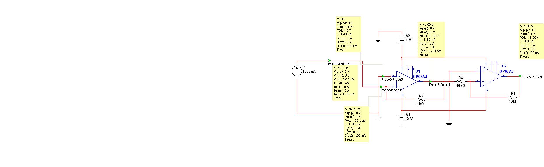
currently i am planning to use i to v converter using op07. Please help me finding how much current can we measure using this transimpedance circuit using op07.Also please let me know which parameter in op07 datasheet mentions the maximum current that can be fed to its input.


Any designs related to this are welcome:

I am posting a design simulated in multisim.


Attachments

  • opamp_ammeter.JPG
    opamp_ammeter.JPG
    59.5 KB · Views: 140

you can use the MAX4080 which is a High-Side, Current-Sense Amplifiers with Voltage Output.

and can amplify from 5 to 60 times.

:)
 

There are a lot of parameters to consider specially in low current end of your design. Major problem with using OP07 might be output swing. Extending your circuit range is easy with adding shunt resistor. OP07 does not have a lot of parameters specified by AD at ±5V supply and is not really good option if you are limited with ±5V only. In AD's selection AD8638 seems to have best performance if bandwidth can be limited (filtered). There are a lot of better choices for low offset opamps with rail to rail performance than old OP07. Feedback resistor and output voltage swing will determine your measurement range. Input is high impedance and you want it to be as high as possible so it does not affect your measurement (there is no maximum input current spec except if you overshoot voltage and protection circuit starts conducting). Increasing feedback resistor to higher value will increase circuit's sensitivity . ~4k might work better. Having more ranges than just two will help accuracy, so you could select even higher value of feedback resistor for lowest ranges. Higher ranges, as I already mentioned , can be solved with shunt resistor with feedback resistor kept at 2k or higher. Adding capacitance in parallel to feedback resistor will decrease bandwidth and with it noise as well. Just to mention, in circuits where OP07 would perform well there is improved version OP177 that might be even easier to find and cheaper.
 
Please help me finding how much current can we measure using this transimpedance circuit using op07.Also please let me know which parameter in op07 datasheet mentions the maximum current that can be fed to its input.

Looks like you're ignoring an important property of the transimpedance circuit. The current has to be sourced by the OP output! So the current range of the circuit is limited to e.g. 10 mA. For higher currents, you have to use shunt resistors with voltage amplifier.
 
Status
Not open for further replies.

Similar threads

Part and Inventory Search

Welcome to EDABoard.com

Sponsor

Back
Top